Basic Operation
Switches
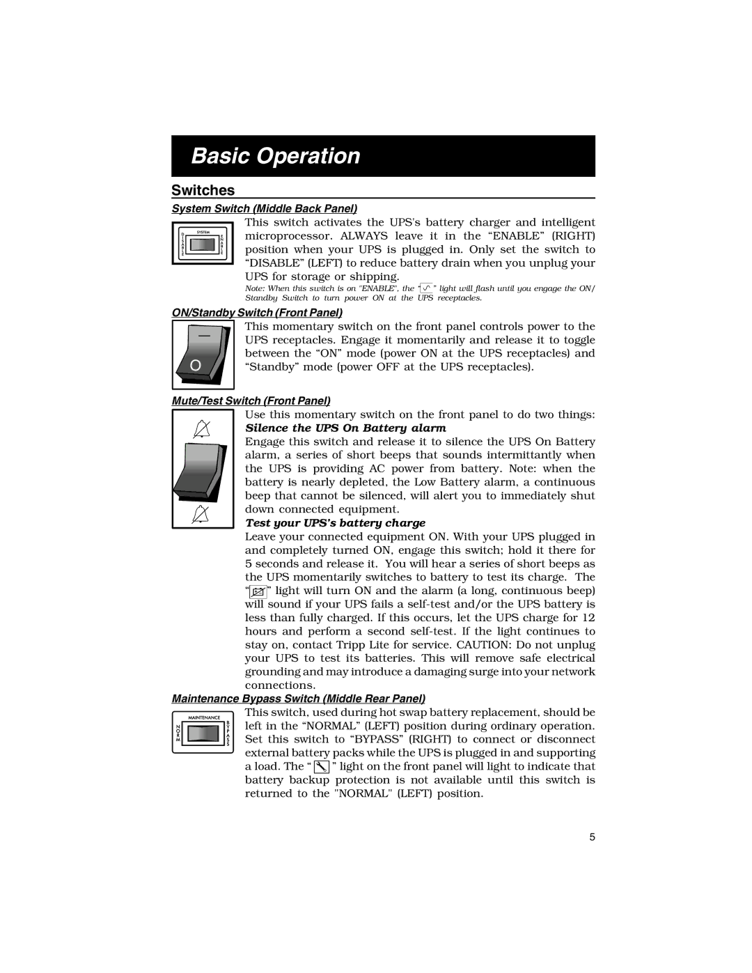
System Switch (Middle Back Panel)
This switch activates the UPS's battery charger and intelligent microprocessor. ALWAYS leave it in the “ENABLE” (RIGHT) position when your UPS is plugged in. Only set the switch to “DISABLE” (LEFT) to reduce battery drain when you unplug your UPS for storage or shipping.
Note: When this switch is on "ENABLE", the “![]() ” light will flash until you engage the ON/ Standby Switch to turn power ON at the UPS receptacles.
” light will flash until you engage the ON/ Standby Switch to turn power ON at the UPS receptacles.
ON/Standby Switch (Front Panel)
This momentary switch on the front panel controls power to the
—UPS receptacles. Engage it momentarily and release it to toggle
between the “ON” mode (power ON at the UPS receptacles) and “Standby” mode (power OFF at the UPS receptacles).
Mute/Test Switch (Front Panel)
Use this momentary switch on the front panel to do two things:
Silence the UPS On Battery alarm
Engage this switch and release it to silence the UPS On Battery alarm, a series of short beeps that sounds intermittantly when the UPS is providing AC power from battery. Note: when the battery is nearly depleted, the Low Battery alarm, a continuous beep that cannot be silenced, will alert you to immediately shut down connected equipment.
Test your UPS’s battery charge
Leave your connected equipment ON. With your UPS plugged in and completely turned ON, engage this switch; hold it there for 5 seconds and release it. You will hear a series of short beeps as the UPS momentarily switches to battery to test its charge. The “![]() ” light will turn ON and the alarm (a long, continuous beep) will sound if your UPS fails a
” light will turn ON and the alarm (a long, continuous beep) will sound if your UPS fails a
Maintenance Bypass Switch (Middle Rear Panel)
This switch, used during hot swap battery replacement, should be left in the “NORMAL” (LEFT) position during ordinary operation. Set this switch to “BYPASS” (RIGHT) to connect or disconnect external battery packs while the UPS is plugged in and supporting a load. The “ ![]()
![]()
![]() ” light on the front panel will light to indicate that battery backup protection is not available until this switch is returned to the "NORMAL" (LEFT) position.
” light on the front panel will light to indicate that battery backup protection is not available until this switch is returned to the "NORMAL" (LEFT) position.
5