Feature Identification
Identify the premium features on your specific model and quickly locate instructions on how to maximize their use.
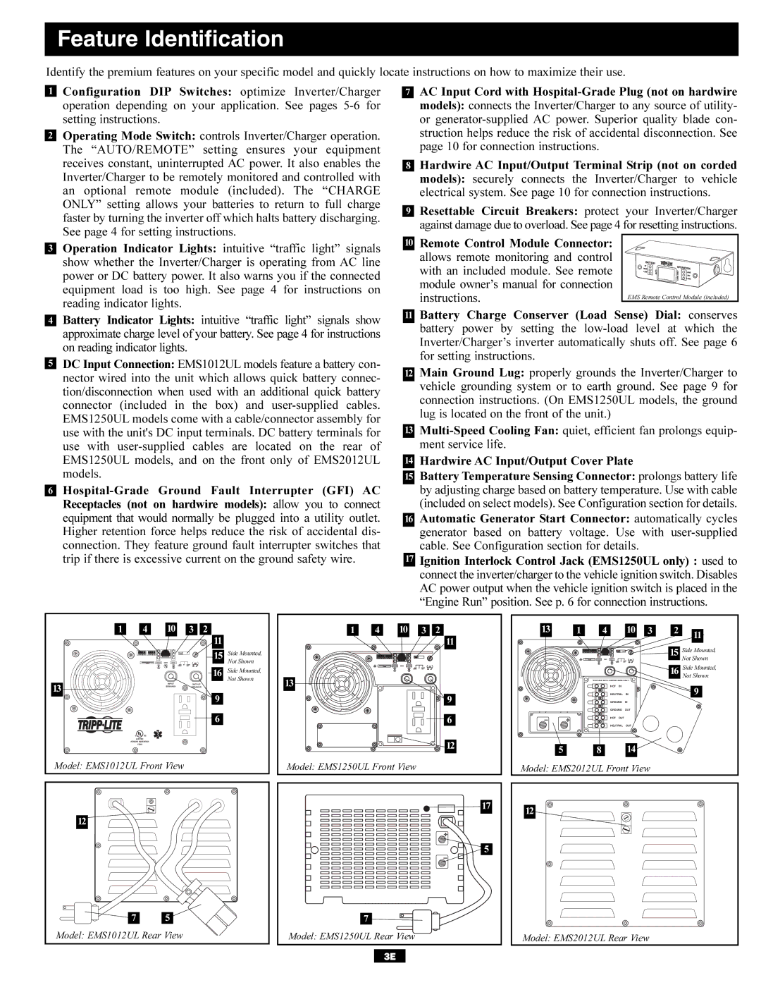
1 | Configuration DIP Switches: optimize Inverter/Charger | 7 |
| AC Input Cord with | |||||||
| operation depending on your application. See pages |
|
|
| models): connects the Inverter/Charger to any source of utility- | ||||||
| setting instructions. |
|
|
|
|
| or | ||||
| Operating Mode Switch: controls Inverter/Charger operation. |
|
|
| struction helps reduce the risk of accidental disconnection. See | ||||||
2 |
|
| |||||||||
|
|
| page 10 for connection instructions. | ||||||||
| The “AUTO/REMOTE” setting ensures your equipment |
|
|
| |||||||
|
|
|
|
|
|
|
| ||||
| receives constant, uninterrupted AC power. It also enables the |
|
|
| Hardwire AC Input/Output Terminal Strip (not on corded | ||||||
| 8 |
| |||||||||
| Inverter/Charger to be remotely monitored and controlled with |
|
|
| models): securely connects the Inverter/Charger to vehicle | ||||||
| an optional remote module (included). The “CHARGE |
|
|
| electrical system. See page 10 for connection instructions. | ||||||
| ONLY” setting allows your batteries to return to full charge |
|
|
| Resettable Circuit Breakers: protect your Inverter/Charger | ||||||
| 9 |
| |||||||||
| faster by turning the inverter off which halts battery discharging. |
| |||||||||
|
|
|
| against damage due to overload. See page 4 for resetting instructions. | |||||||
| See page 4 for setting instructions. |
|
|
|
|
| |||||
|
|
|
|
|
| Remote Control Module Connector: |
| ||||
| Operation Indicator Lights: intuitive “traffic light” signals | 10 |
|
| |||||||
3 | |||||||||||
|
|
| allows remote monitoring and control |
| |||||||
| show whether the Inverter/Charger is operating from AC line |
|
|
|
| ||||||
|
|
|
| with an included module. See remote |
| ||||||
| power or DC battery power. It also warns you if the connected |
|
|
|
| ||||||
|
|
|
| module owner’s manual for connection |
| ||||||
| equipment load is too high. See | page 4 | for instructions on |
|
|
|
| ||||
|
|
|
| instructions. |
| EMS Remote Control Module (included) | |||||
| reading indicator lights. |
|
|
|
|
|
| ||||
|
|
|
|
|
| Battery | Charge | Conserver (Load Sense) Dial: conserves | |||
| Battery Indicator Lights: intuitive | “traffic | light” signals show | 11 |
| ||||||
4 | |||||||||||
|
|
| battery | power by | setting the | ||||||
| approximate charge level of your battery. See page 4 for instructions |
|
|
| |||||||
|
|
|
| Inverter/Charger’s inverter automatically shuts off. See page 6 | |||||||
| on reading indicator lights. |
|
|
|
|
| |||||
|
|
|
|
|
| for setting instructions. | |||||
| DC Input Connection: EMS1012UL models feature a battery con- |
|
|
| |||||||
5 |
|
| |||||||||
|
|
| Main Ground Lug: properly grounds the Inverter/Charger to | ||||||||
| nector wired into the unit which allows quick battery connec- | 12 |
| ||||||||
|
|
|
| vehicle grounding system or to earth ground. See page 9 for | |||||||
| tion/disconnection when used with an additional quick battery |
|
|
| |||||||
|
|
|
| connection instructions. (On EMS1250UL models, the ground | |||||||
| connector (included in the box) | and |
|
|
| ||||||
|
|
|
| lug is located on the front of the unit.) | |||||||
| EMS1250UL models come with a cable/connector assembly for |
|
|
| |||||||
|
|
|
|
|
|
|
| ||||
| use with the unit's DC input terminals. DC battery terminals for | 13 |
| ||||||||
| use with |
|
|
| ment service life. |
|
| ||||
| EMS1250UL models, and on the front only of EMS2012UL |
|
|
| Hardwire AC Input/Output Cover Plate | ||||||
| 14 |
| |||||||||
| models. |
|
|
|
|
| Battery Temperature Sensing Connector: prolongs battery life | ||||
|
|
| 15 |
| |||||||
6 | Interrupter (GFI) AC |
|
|
| by adjusting charge based on battery temperature. Use with cable | ||||||
| Receptacles (not on hardwire models): allow you to connect |
|
|
| (included on select models). See Configuration section for details. | ||||||
| equipment that would normally be plugged into a utility outlet. |
|
|
| Automatic Generator Start Connector: automatically cycles | ||||||
| 16 |
| |||||||||
| Higher retention force helps reduce the risk of accidental dis- |
|
|
| generator based on battery voltage. Use with | ||||||
| connection. They feature ground fault interrupter switches that |
|
|
| cable. See Configuration section for details. | ||||||
| trip if there is excessive current on the ground safety wire. |
| 17 |
| Ignition Interlock Control Jack (EMS1250UL only) : used to | ||||||
|
|
|
|
|
|
| connect the inverter/charger to the vehicle ignition switch. Disables | ||||
|
|
|
|
|
|
| AC power output when the vehicle ignition switch is placed in the | ||||
|
|
|
|
|
|
| “Engine Run” position. See p. 6 for connection instructions. | ||||
1 | 4 | 10 | 3 | 2 | 1 | 4 | 10 | 3 | 2 | 13 | 1 | 4 | 10 | 3 | 2 | 11 |
|
|
|
| 11 |
|
|
|
|
| 11 |
|
|
|
|
| |
|
|
|
|
|
|
|
|
|
|
|
|
|
|
|
15 | Side Mounted, | 15 | Side Mounted, |
Not Shown | |||
| Not Shown |
|
|
|
| 16 | Side Mounted, |
|
|
|
| 16 | Side Mounted, |
|
|
|
|
|
| Not Shown | |||
|
|
| Not Shown | 13 |
|
| “FOR USE WITH COPPER WIRE ONLY” |
| |
13 | INPUT | OUTPUT |
|
|
| HOT IN |
|
| |
BREAKER | BREAKER |
|
|
|
| 9 | |||
|
| 9 |
|
| 9 |
| NEUTRAL | IN | |
|
|
|
|
| GROUND | IN |
| ||
|
| 6 |
|
| 6 |
| GROUND | OUT |
|
|
|
|
|
| HOT OUT |
|
| ||
|
|
|
|
|
|
| NEUTRAL | OUT |
|
| C UL US |
|
|
|
|
|
|
|
|
| LISTED |
|
|
|
|
|
|
|
|
| POWER INVERTER |
|
|
| 12 |
|
|
|
|
| 1DA8 |
|
|
|
|
|
|
| |
|
|
|
|
|
| 5 | 8 | 14 |
|
Model: EMS1012UL Front View |
|
| Model: EMS1250UL Front View |
| Model: EMS2012UL Front View |
| |||
12 |
|
7 | 5 |
Model: EMS1012UL Rear View | |
17 |
5 |
7 |
Model: EMS1250UL Rear View |
3E |
12 |
Model: EMS2012UL Rear View |