Configuration (continued)
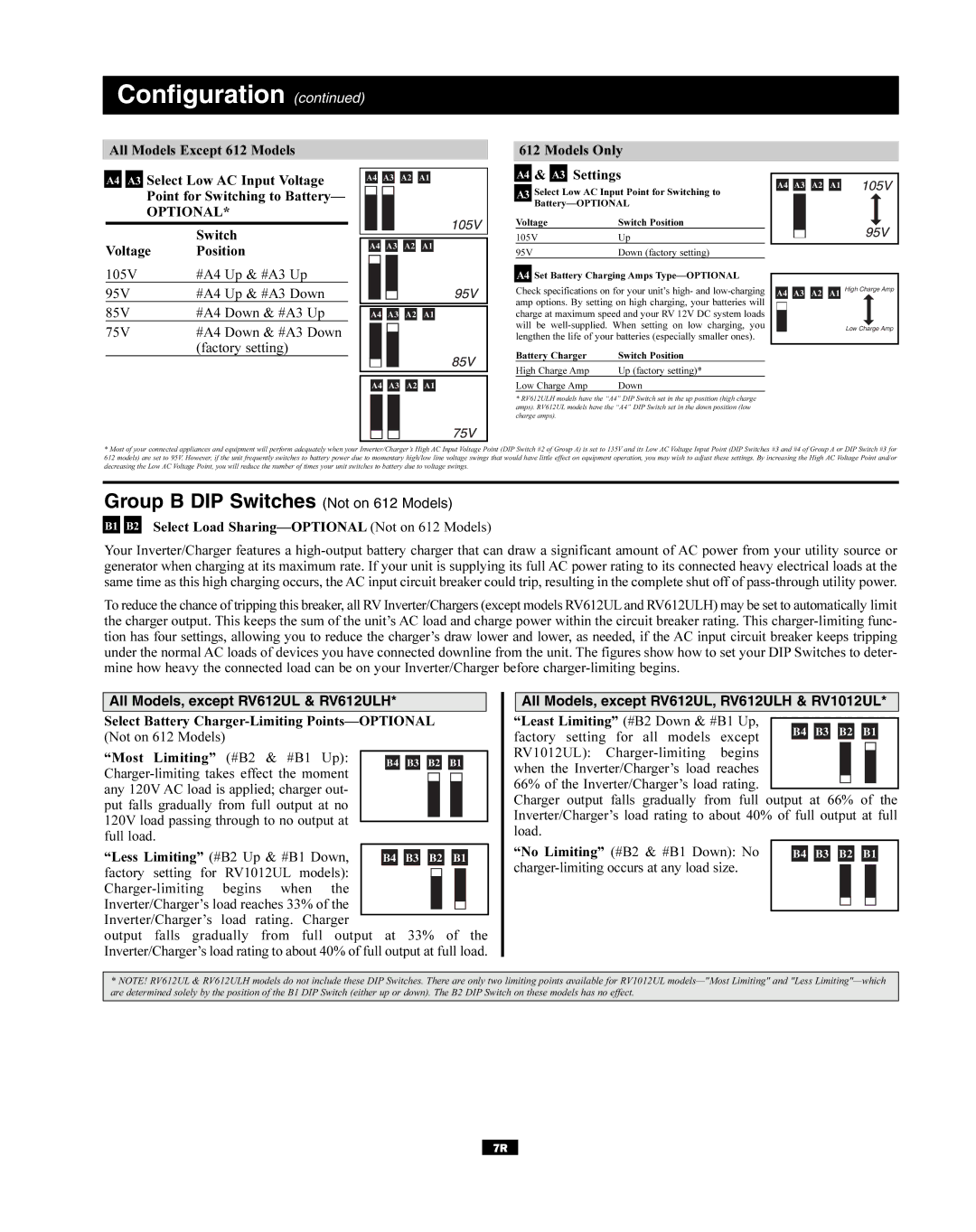
All Models Except 612 Models
A4 A3 Select Low AC Input Voltage Point for Switching to Battery—
OPTIONAL*
| Switch |
Voltage | Position |
A4 A3 A2 A1
A4 A3 A2 A1
612 Models Only
A4 & A3 Settings
A3 Select Low AC Input Point for Switching to
Voltage | Switch Position |
105V | Up |
95V | Down (factory setting) |
A4 A3 A2 A1
105V | #A4 Up & #A3 Up |
95V | #A4 Up & #A3 Down |
85V | #A4 Down & #A3 Up |
75V | #A4 Down & #A3 Down |
| (factory setting) |
A4 A3 A2 A1
A4 Set Battery Charging Amps Type—OPTIONAL
Check specifications on for your unit’s high- and
Battery Charger | Switch Position |
High Charge Amp | Up (factory setting)* |
A4 A3 A2 A1 High Charge Amp
Low Charge Amp
A4 A3 A2 A1
Low Charge Amp | Down |
*RV612ULH models have the “A4” DIP Switch set in the up position (high charge amps). RV612UL models have the “A4” DIP Switch set in the down position (low charge amps).
*Most of your connected appliances and equipment will perform adequately when your Inverter/Charger’s High AC Input Voltage Point (DIP Switch #2 of Group A) is set to 135V and its Low AC Voltage Input Point (DIP Switches #3 and #4 of Group A or DIP Switch #3 for 612 models) are set to 95V. However, if the unit frequently switches to battery power due to momentary high/low line voltage swings that would have little effect on equipment operation, you may wish to adjust these settings. By increasing the High AC Voltage Point and/or decreasing the Low AC Voltage Point, you will reduce the number of times your unit switches to battery due to voltage swings.
Group B DIP Switches (Not on 612 Models)
B1 B2 Select Load Sharing—OPTIONAL (Not on 612 Models)
Your Inverter/Charger features a
To reduce the chance of tripping this breaker, all RVInverter/Chargers (except models RV612ULand RV612ULH) may be set to automatically limit the charger output. This keeps the sum of the unit’s AC load and charge power within the circuit breaker rating. This
All Models, except RV612UL & RV612ULH*
Select Battery
“Most Limiting” (#B2 & #B1 Up):
“Less Limiting” (#B2 Up & #B1 Down,
factory setting for RV1012UL models):
output falls gradually from full output at 33% of the Inverter/Charger’s load rating to about 40% of full output at full load.
All Models, except RV612UL, RV612ULH & RV1012UL*
“Least Limiting” (#B2 Down & #B1 Up, factory setting for all models except RV1012UL):
Charger output falls gradually from full output at 66% of the Inverter/Charger’s load rating to about 40% of full output at full load.
“No Limiting” (#B2 & #B1 Down): No |
|
|
|
|
|
|
|
|
|
|
|
|
|
| B4 |
| B3 |
| B2 |
| B1 |
| |||||
|
|
|
|
|
|
|
|
|
|
|
|
| |
|
|
|
|
|
|
|
|
|
|
|
| ||
|
|
|
|
|
|
|
|
|
|
|
|
|
|
|
|
|
|
|
|
|
|
|
|
|
|
|
|
*NOTE! RV612UL & RV612ULH models do not include these DIP Switches. There are only two limiting points available for RV1012UL
7R