Mounting
WARNING! Mount your Inverter/Charger BEFORE DC battery and AC power connection. Failure to follow these instructions may lead to personal injury and/or damage to the Inverter/Charger and connected systems.
Tripp Lite manufactures a variety of different Inverter/Chargers with a variety of different mounting options for use in vehicular or
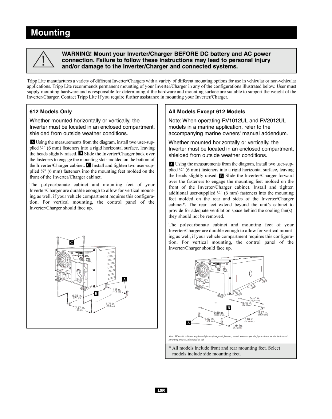
612 Models Only
Whether mounted horizontally or vertically, the Inverter must be located in an enclosed compartment, shielded from outside weather conditions.
AUsing the measurements from the diagram, install two
The polycarbonate cabinet and mounting feet of your Inverter/Charger are durable enough to allow for vertical mount- ing as well, if your vehicle compartment requires this configura- tion. For vertical mounting, the control panel of the Inverter/Charger should face up.
All Models Except 612 Models
Note: When operating RV1012UL and RV2012UL models in a marine application, refer to the accompanying marine owners' manual addendum.
Whether mounted horizontally or vertically, the Inverter must be located in an enclosed compartment, shielded from outside weather conditions.
AUsing the measurements from the diagram, install two
C
B | ▼ |
6.75 in. |
|
(17.1 cm)
A
4.5 in.
(11.4 cm)
The polycarbonate cabinet and mounting feet of your Inverter/Charger are durable enough to allow for vertical mount- ing as well, if your vehicle compartment requires this configura- tion. For vertical mounting, the control panel of the Inverter/Charger should face up.
5.57 in. |
(14.16 cm.) |
| 6.75 in. |
7.87 in. | (17.1 cm) |
| |
(20 cm) |
|
|
|
| 9.59 in. |
|
|
| (24.35 cm.) |
|
|
| B |
| 9.59 in. | 5.87 in. | |
| (24.35 cm.) | (14.91 cm.) | |
| 5.57 in. | ▼ | 5.87 in. |
A | (14.16 cm.) |
| (14.91 cm.) |
|
| 1.64 in. | |
|
|
| |
|
|
| (4.15 cm.) |
Note: RV model cabinets may have different front panel features, but all mount as per the figure above, or via the Lateral Mounting Bracket, illustrated at left.
* All models include front and rear mounting feet. Select models include side mounting feet.
10R