Configuration (continued)
B3 Select Equalize Battery
(Not on 612 Models)
This DIP Switch is momentarily engaged |
|
|
|
|
|
|
|
|
|
|
|
|
| B4 |
| B3 |
| B2 |
| B1 | Reset | ||||
to begin the process of equalizing the |
|
|
|
|
|
|
|
|
|
|
|
|
|
|
|
|
|
|
|
|
|
|
| ||
charge state of your battery’s cells by time- |
|
|
|
|
|
|
|
|
|
|
|
|
limited overcharge of all cells. This can |
|
|
|
|
|
|
|
|
|
| Equalize | |
extend the useful life of certain types of |
|
|
|
|
|
|
|
|
|
|
|
|
|
|
|
|
|
|
|
|
|
|
|
| |
batteries; consult with your battery’s manufacturer to determine if your batteries could benefit from this process. The charge equaliza- tion process is automatic; once started, it can only be stopped by removing the input power.
Setting Procedure
•Move to “Equalize” (DOWN) position for three seconds.
•Move to “Reset” (UP) position and leave it there. This is the factory default setting.
CAUTION: Do not leave DIP switch #B3 in the down position after beginning process. Battery charge equalization should only be performed in strict accordance with the battery manufacturer’s instructions and specifications.
Battery Charge | Switch Position |
Reset | Up (factory setting) |
Equalize |
B4 Set Battery Charging
Check specifications for your unit’s high- and
maximum speed and your RV 12V DC system loads will be
setting on low charging, you lengthen the life of your batteries (especially smaller ones).
Battery Charger | Switch Position |
Low Charge Amps | Up |
High Charge Amps | Down (factory setting) |
CAUTION: When switching to the High Charge Amp setting, the user must ensure that the amp hour capacity of their battery system exceeds the amperage of the High Charge Amp setting or the batteries may be damaged or degraded.
Set Battery Charge Conserver (Load Sense)
In order to save battery power, the unit’s inverter automatically shuts off in the absence of any power demand from connected equipment or appliances (the electrical load). When the unit detects a load, it automatically turns its inverter function on.
Users may choose the minimum load the Inverter/Charger will detect by adjusting the Battery Charge Conserver Dial (see diagram). Using a small tool, turn the dial clockwise to lower the minimum load that will be detected, causing the inverter to turn on for smaller loads. When the dial is turned fully clockwise, the inverter will operate even when there is no load. Turn the
dial counterclockwise to increase the minimum load that will be detected, causing the inverter to stay off until the new minimum load is reached.
Note: the factory setting for the dial is fully clockwise. However, based on the threshold load to which you’d like the inverter to respond, you should adjust the dial counterclockwise to reduce its sensi- tivity until the inverter is active only when connected equipment or appliances are actually in use.
Connect Remote
All models feature an
Connect Battery Temperature Sensing
The battery temperature sensing function prolongs battery life by adjusting the charge float voltage level based on battery temperature. Connect the sensor cable (the cable, included with select models, has an RJ style connector on one end and a black sensor on the other) to the RJ style jack located on the side of the Inverter/Charger labeled “Remote Temp. Sense.” With
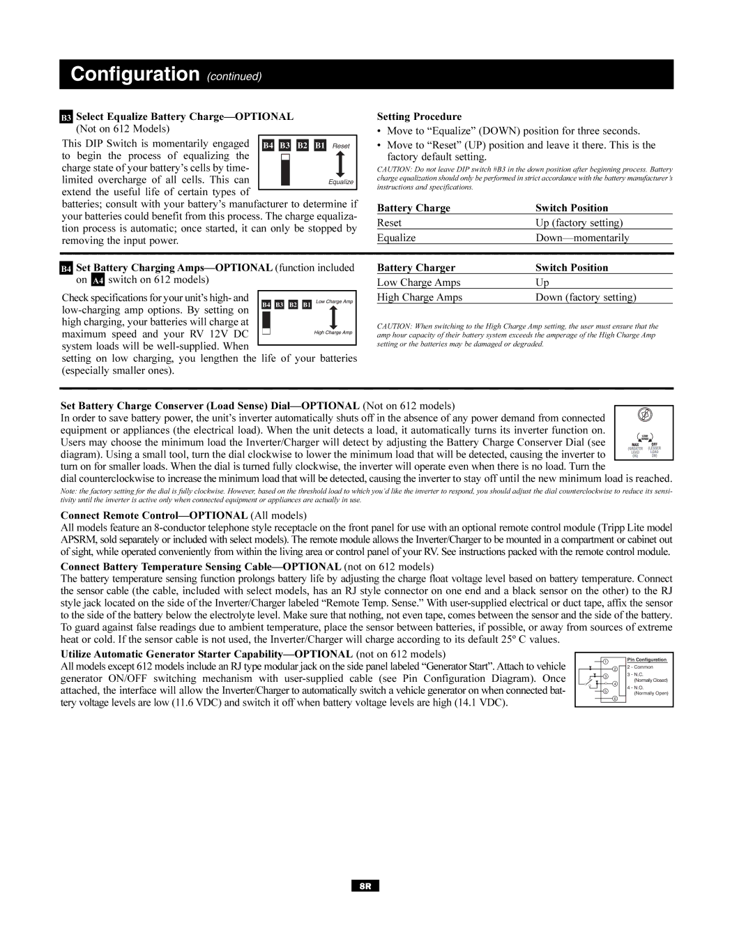
Utilize Automatic Generator Starter
All models except 612 models include an RJ type modular jack on the side panel labeled “Generator Start”. Attach to vehicle generator ON/OFF switching mechanism with
1 |
2 |
3 |
4 |
5 |
6 |
Pin Configuration
2 - Common
3 - N.C.
(Normally Closed)
4 - N.O.
(Normally Open)
8R