User Interface
|
|
|
|
|
|
|
|
|
|
|
|
|
|
|
|
|
|
|
|
|
|
|
|
|
|
|
|
|
|
|
|
|
|
|
|
|
|
|
|
|
|
|
|
|
|
|
|
|
|
|
|
|
|
|
|
|
|
|
|
|
|
|
|
|
|
|
|
|
|
|
|
|
|
|
|
|
|
|
|
|
|
|
|
|
|
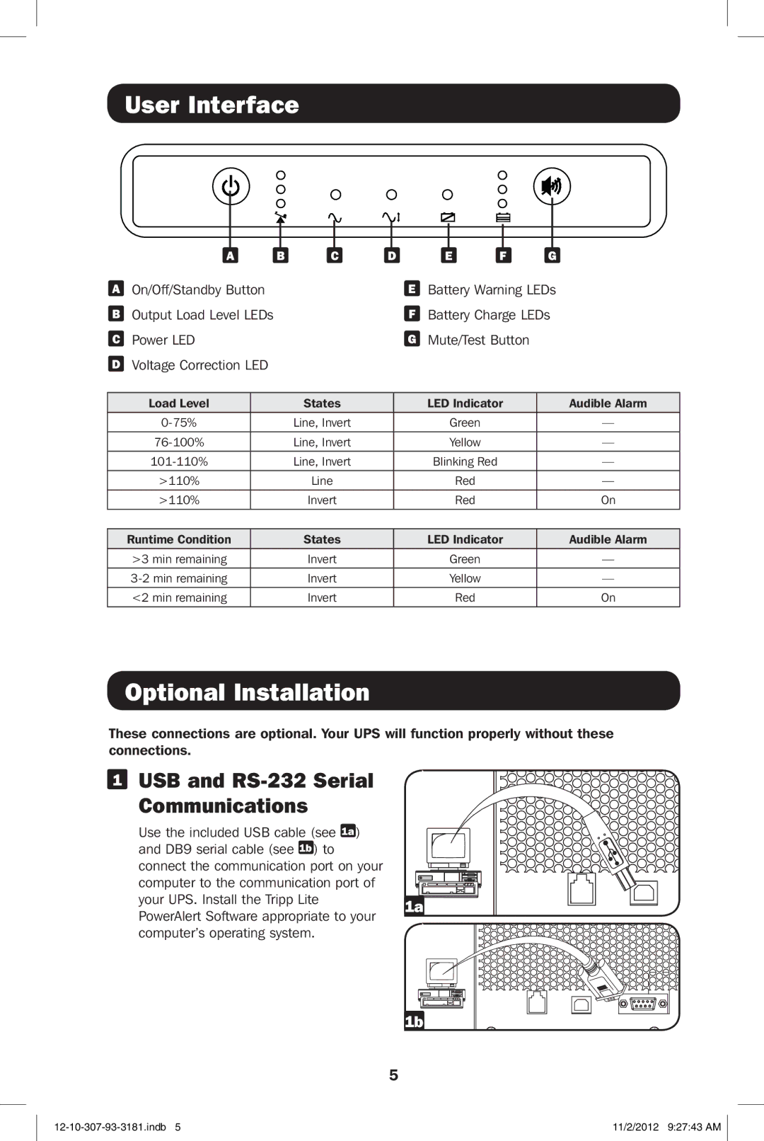
| A | B | C | D | E | F | G | ||||||||
A | On/Off/Standby Button |
|
|
|
|
|
| E | Battery Warning LEDs | |||||||
B Output Load Level LEDs |
|
|
|
|
|
| F | Battery Charge LEDs | ||||||||
C | Power LED |
|
|
|
|
|
| G | Mute/Test Button |
|
| |||||
DVoltage Correction LED
Load Level | States | LED Indicator | Audible Alarm |
Line, Invert | Green | — | |
|
|
|
|
Line, Invert | Yellow | — | |
Line, Invert | Blinking Red | — | |
>110% | Line | Red | — |
>110% | Invert | Red | On |
|
|
|
|
Runtime Condition | States | LED Indicator | Audible Alarm |
>3 min remaining | Invert | Green | — |
|
|
|
|
Invert | Yellow | — | |
|
|
|
|
<2 min remaining | Invert | Red | On |
Optional Installation
These connections are optional. Your UPS will function properly without these connections.
1 USB and RS-232 Serial
Communications
Use the included USB cable (see 1a ) |
| |
and DB9 serial cable (see 1b ) to |
| |
connect the communication port on your |
| |
computer to the communication port of |
| |
your UPS. Install the Tripp Lite | 1a | |
PowerAlert Software appropriate to your | ||
| ||
computer’s operating system. |
|
1b |
5
11/2/2012 9:27:43 AM |