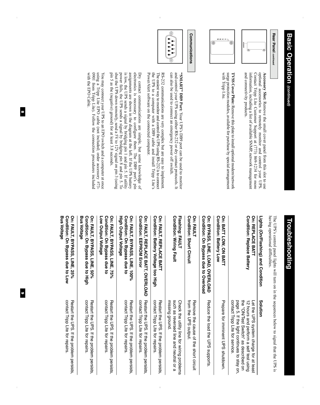
SU3000XL, SU1000XL, SU2200XL specifications
Tripp Lite is known for its reliable power protection solutions, and the SU3000XL, SU2200XL, and SU1000XL series of uninterruptible power supplies (UPS) exemplify this commitment. Each model is designed to provide high-performance power protection for servers, networking equipment, and critical electronic devices, ensuring that operational continuity is maintained even during power interruptions.The SU3000XL is a robust solution offering 3000VA / 2400W capacity. It features sine wave output, which is essential for the safe functioning of sensitive electronics. With multiple output options, including a variety of outlets, the SU3000XL supports a wide range of devices. This model also incorporates advanced technologies like Automatic Voltage Regulation (AVR), which stabilizes voltage levels, ensuring connected devices receive clean and consistent power. Additionally, the UPS is equipped with an LCD display, providing real-time monitoring of power conditions, battery status, and load levels.
The SU2200XL presents a versatile 2200VA / 1980W capacity. Similar to the SU3000XL, it offers sine wave output and AVR technology. Its compact design makes it suitable for smaller setups without compromising power availability. The SU2200XL is an ideal choice for businesses or home environments that require dependable backup power for vital systems while maintaining energy efficiency. Built-in USB and serial connectivity allow users to integrate with management software, enabling seamless power management and monitoring.
For environments with lower power needs, the SU1000XL delivers a capacity of 1000VA / 800W. This model is particularly well-suited for desktops, workstations, and smaller network devices. Despite its smaller capacity, the SU1000XL does not skimp on features. It also includes sine wave output and AVR technology, providing the essential power protection that Tripp Lite is known for. An easy-to-read LED display presents vital information at a glance, making it user-friendly.
All three models boast hot-swappable batteries, allowing for easy maintenance without downtime. Furthermore, they come with a variety of safety features, including surge protection and short circuit protection, enhancing their reliability. With a focus on durability, Tripp Lite’s UPS systems are built to last, backed by a solid warranty and customer support. Overall, the SU3000XL, SU2200XL, and SU1000XL ensure that users can trust their power sources, no matter the requirements.

