AC Input/Output Connection
To avoid overloading your Inverter, match the power requirements of the equipment you plan to run at any one time (add their total watts) with the output wattage capacity of your Inverter model. Do not confuse “continuous” wattage with “peak” wattage ratings. Most electric motors require extra power at
* Actual duration depends on model, battery age, battery charge level and ambient temperature.
Connection for Models with Cords and Receptacles
Plug the Inverter’s AC input cord into an extension cord and then into an outlet providing 120V AC, 60Hz. power. Make sure that the circuit you connect your Inverter to has adequate overload protection, such as a circuit breaker or a fuse. Plug your equipment into the Inverter’s AC receptacles.
WARNING! Consult a qualified electrician and follow all applicable electrical codes and requirements for hardwire connection. Disconnect both DC input and AC utility supply before attempting hardwiring.
Connection for Models with Hardwire Terminals
Output Connection Requirement: UL requires that the output terminals of all hardwire Inverter models must be connected to
(required receptacle manufacturer/model series: Leviton 6599).
Dual Input/Output Models
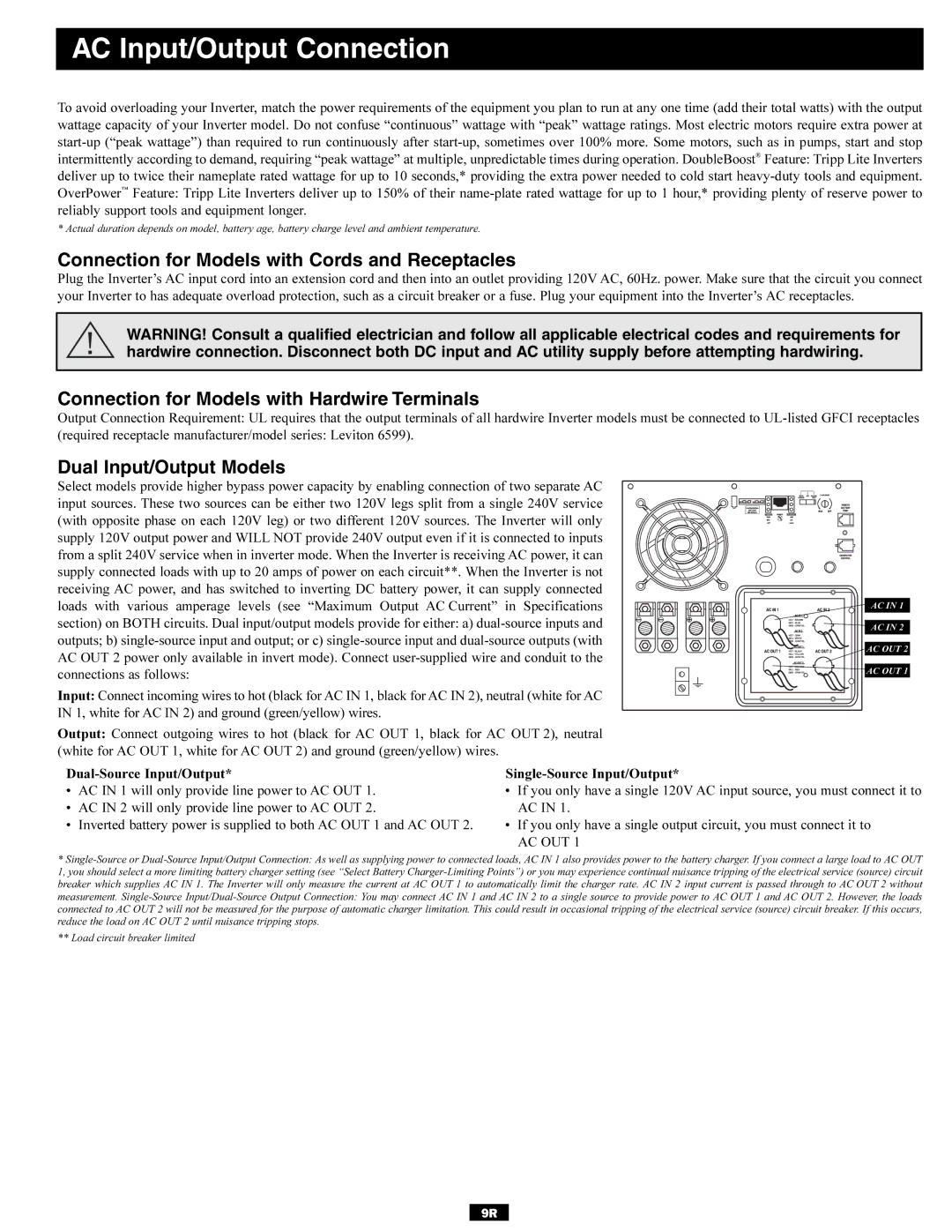
Select models provide higher bypass power capacity by enabling connection of two separate AC input sources. These two sources can be either two 120V legs split from a single 240V service (with opposite phase on each 120V leg) or two different 120V sources. The Inverter will only supply 120V output power and WILL NOT provide 240V output even if it is connected to inputs from a split 240V service when in inverter mode. When the Inverter is receiving AC power, it can supply connected loads with up to 20 amps of power on each circuit**. When the Inverter is not receiving AC power, and has switched to inverting DC battery power, it can supply connected loads with various amperage levels (see “Maximum Output AC Current” in Specifications section) on BOTH circuits. Dual input/output models provide for either: a)
Input: Connect incoming wires to hot (black for AC IN 1, black for AC IN 2), neutral (white for AC IN 1, white for AC IN 2) and ground (green/yellow) wires.
Output: Connect outgoing wires to hot (black for AC OUT 1, black for AC OUT 2), neutral (white for AC OUT 1, white for AC OUT 2) and ground (green/yellow) wires.
AC IN 1 |
AC IN 2 |
AC OUT 2 |
AC OUT 1 |
•AC IN 1 will only provide line power to AC OUT 1.
•AC IN 2 will only provide line power to AC OUT 2.
•Inverted battery power is supplied to both AC OUT 1 and AC OUT 2.
•If you only have a single 120V AC input source, you must connect it to AC IN 1.
•If you only have a single output circuit, you must connect it to
AC OUT 1
*
** Load circuit breaker limited
9R