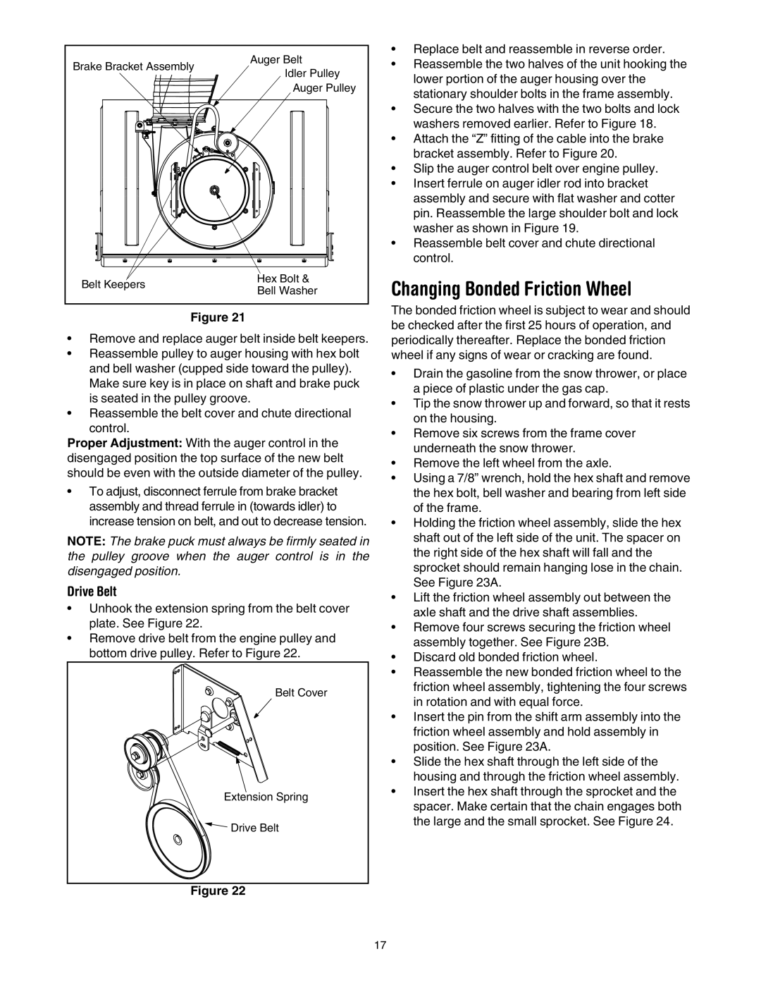
| Auger Belt | • Replace belt and reassemble in reverse order. | |
Brake Bracket Assembly | • Reassemble the two halves of the unit hooking the | ||
Idler Pulley | |||
| lower portion of the auger housing over the | ||
| Auger Pulley | ||
| stationary shoulder bolts in the frame assembly. | ||
|
| ||
|
| • Secure the two halves with the two bolts and lock | |
|
| washers removed earlier. Refer to Figure 18. | |
|
| • Attach the “Z” fitting of the cable into the brake | |
|
| bracket assembly. Refer to Figure 20. | |
|
| • Slip the auger control belt over engine pulley. | |
|
| • Insert ferrule on auger idler rod into bracket | |
|
| assembly and secure with flat washer and cotter | |
|
| pin. Reassemble the large shoulder bolt and lock | |
|
| washer as shown in Figure 19. | |
|
| • Reassemble belt cover and chute directional | |
|
| control. | |
Belt Keepers | Hex Bolt & | Changing Bonded Friction Wheel | |
Bell Washer | |||
|
Figure 21 | The bonded friction wheel is subject to wear and should | |
be checked after the first 25 hours of operation, and | ||
• Remove and replace auger belt inside belt keepers. | ||
periodically thereafter. Replace the bonded friction | ||
• Reassemble pulley to auger housing with hex bolt | wheel if any signs of wear or cracking are found. | |
and bell washer (cupped side toward the pulley). | • Drain the gasoline from the snow thrower, or place | |
Make sure key is in place on shaft and brake puck | ||
a piece of plastic under the gas cap. | ||
is seated in the pulley groove. | ||
• Tip the snow thrower up and forward, so that it rests | ||
• Reassemble the belt cover and chute directional | ||
on the housing. | ||
control. | ||
• Remove six screws from the frame cover | ||
Proper Adjustment: With the auger control in the | ||
underneath the snow thrower. | ||
disengaged position the top surface of the new belt | ||
• Remove the left wheel from the axle. | ||
should be even with the outside diameter of the pulley. | ||
• Using a 7/8” wrench, hold the hex shaft and remove | ||
• To adjust, disconnect ferrule from brake bracket | ||
the hex bolt, bell washer and bearing from left side | ||
assembly and thread ferrule in (towards idler) to | of the frame. | |
increase tension on belt, and out to decrease tension. | • Holding the friction wheel assembly, slide the hex | |
NOTE: The brake puck must always be firmly seated in | shaft out of the left side of the unit. The spacer on | |
the pulley groove when the auger control is in the | the right side of the hex shaft will fall and the | |
disengaged position. | sprocket should remain hanging lose in the chain. | |
Drive Belt | See Figure 23A. | |
• Lift the friction wheel assembly out between the | ||
• Unhook the extension spring from the belt cover | ||
axle shaft and the drive shaft assemblies. | ||
plate. See Figure 22. | ||
• Remove four screws securing the friction wheel | ||
• Remove drive belt from the engine pulley and | ||
assembly together. See Figure 23B. | ||
bottom drive pulley. Refer to Figure 22. | ||
• Discard old bonded friction wheel. | ||
| ||
| • Reassemble the new bonded friction wheel to the | |
Belt Cover | friction wheel assembly, tightening the four screws | |
in rotation and with equal force. | ||
| ||
| • Insert the pin from the shift arm assembly into the | |
| friction wheel assembly and hold assembly in | |
| position. See Figure 23A. | |
| • Slide the hex shaft through the left side of the | |
| housing and through the friction wheel assembly. | |
Extension Spring | • Insert the hex shaft through the sprocket and the | |
spacer. Make certain that the chain engages both | ||
| ||
Drive Belt | the large and the small sprocket. See Figure 24. | |
| ||
Figure 22 |
|
17