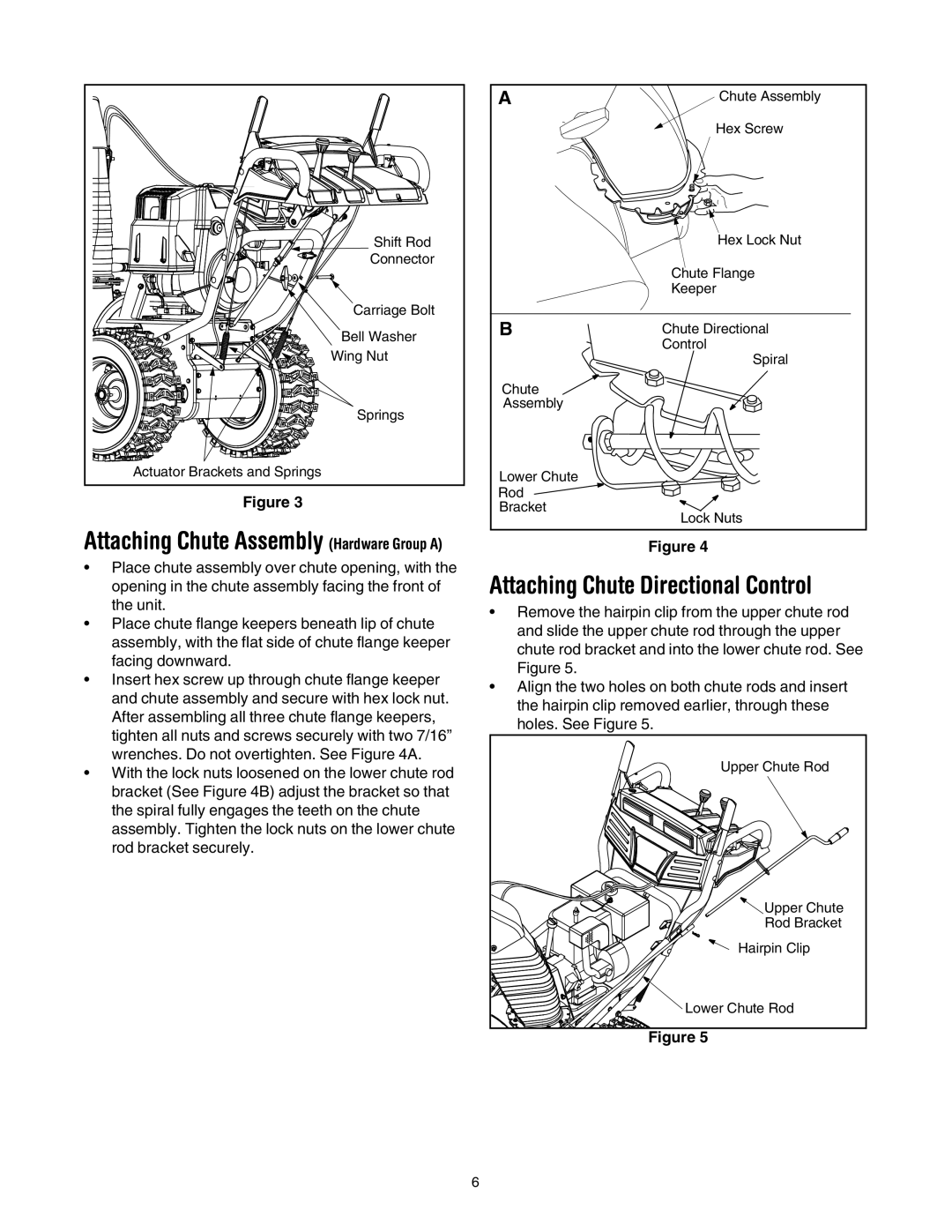
Shift Rod |
Connector |
Carriage Bolt |
Bell Washer |
Wing Nut |
Springs |
Actuator Brackets and Springs |
Figure 3
Attaching Chute Assembly (Hardware Group A)
•Place chute assembly over chute opening, with the opening in the chute assembly facing the front of the unit.
•Place chute flange keepers beneath lip of chute assembly, with the flat side of chute flange keeper facing downward.
•Insert hex screw up through chute flange keeper and chute assembly and secure with hex lock nut. After assembling all three chute flange keepers, tighten all nuts and screws securely with two 7/16” wrenches. Do not overtighten. See Figure 4A.
•With the lock nuts loosened on the lower chute rod bracket (See Figure 4B) adjust the bracket so that the spiral fully engages the teeth on the chute assembly. Tighten the lock nuts on the lower chute rod bracket securely.
A | Chute Assembly |
| Hex Screw |
| Hex Lock Nut |
| Chute Flange |
| Keeper |
B | Chute Directional |
| Control |
| Spiral |
Chute |
|
Assembly |
|
Lower Chute |
|
Rod |
|
Bracket | Lock Nuts |
|
Figure 4
Attaching Chute Directional Control
•Remove the hairpin clip from the upper chute rod and slide the upper chute rod through the upper chute rod bracket and into the lower chute rod. See Figure 5.
•Align the two holes on both chute rods and insert the hairpin clip removed earlier, through these holes. See Figure 5.
Upper Chute Rod
![]() Upper Chute
Upper Chute
Rod Bracket
Hairpin Clip
![]()
![]() Lower Chute Rod
Lower Chute Rod
Figure 5
6