Section 5: Maintenance
Transmission Gear Oil Maintenance
A. Check for Transmission Oil Leaks
After the first two (2) hours of brand- new operation, check the transmission for oil leaks. Thereafter, check for leaks every 25 operating hours. Specifically, inspect the following areas for signs of leaks or seepage:
1. There are oil seals on each side of the |
transmission housing where the tine shaft |
passes through the housing. Examine |
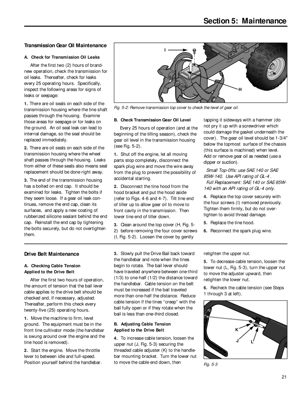
I
H
Fig. 5-2: Remove transmission top cover to check the level of gear oil.
those areas for seepage or for leaks on |
the ground. An oil seal leak can lead to |
internal damage, so the seal should be |
replaced immediately. |
2. There are oil seals on each side of the |
transmission housing where the wheel |
shaft passes through the housing. Leaks |
from either of these seals also means seal |
replacement should be done right away. |
3. The end of the transmission housing |
has a bolted on end cap. It should be |
examined for leaks. Tighten the bolts if |
they seem loose. If a gear oil leak con- |
tinues, remove the end cap, clean its |
surfaces, and apply a new coating of |
rubberized silicone sealant behind the end |
cap. Reinstall the end cap by tightening |
the bolts securely, but do not overtighten |
them. |
B. Check Transmission Gear Oil Level
Every 25 hours of operation (and at the beginning of the tilling season), check the gear oil level in the transmission housing (see Fig.
1.Shut off the engine, let all moving parts stop completely, disconnect the spark plug wire and move the wire away from the plug to prevent the possibility of accidental starting.
2.Disconnect the tine hood from the hood bracket and put the hood aside (refer to Figs.
3.Clean around the top cover (H, Fig. 5-
2) before removing the four cover screws (I, Fig.
tapping it sideways with a hammer (do not pry it up with a screwdriver which could damage the gasket underneath the cover). The gear oil level should be
Small
Full Replacement: SAE 140 or SAE 85W- 140 with an API rating of
4.Replace the top cover securely with the four screws (I) removed previously. Tighten them firmly, but do not over- tighten to avoid thread damage.
5.Replace the tine hood.
6.Reconnect the spark plug wire.
Drive Belt Maintenance
A.Checking Cable Tension Applied to the Drive Belt
After the first two hours of operation, the amount of tension that the bail lever cable applies to the drive belt should be checked and, if necessary, adjusted. Thereafter, perform this check every
1.Move the machine to firm, level ground. The equipment must be in the front tine cultivator mode (the handlebar is swung around over the engine and the tine hood is removed).
2.Start the engine. Move the throttle lever to between idle and
3.Slowly pull the Drive Bail back toward the handlebar and note when the tines begin to rotate. The bail lever should have traveled anywhere between
B.Adjusting Cable Tension Applied to the Drive Belt
4.To increase cable tension, loosen the upper nut (J, Fig.
retighten the upper nut.
5.To decrease cable tension, loosen the lower nut (L, Fig.
6.Recheck the cable tension (see Steps
1through 3 at left).
K |
|
J | L |
Fig. |
|
21
