Section
3Features and Controls
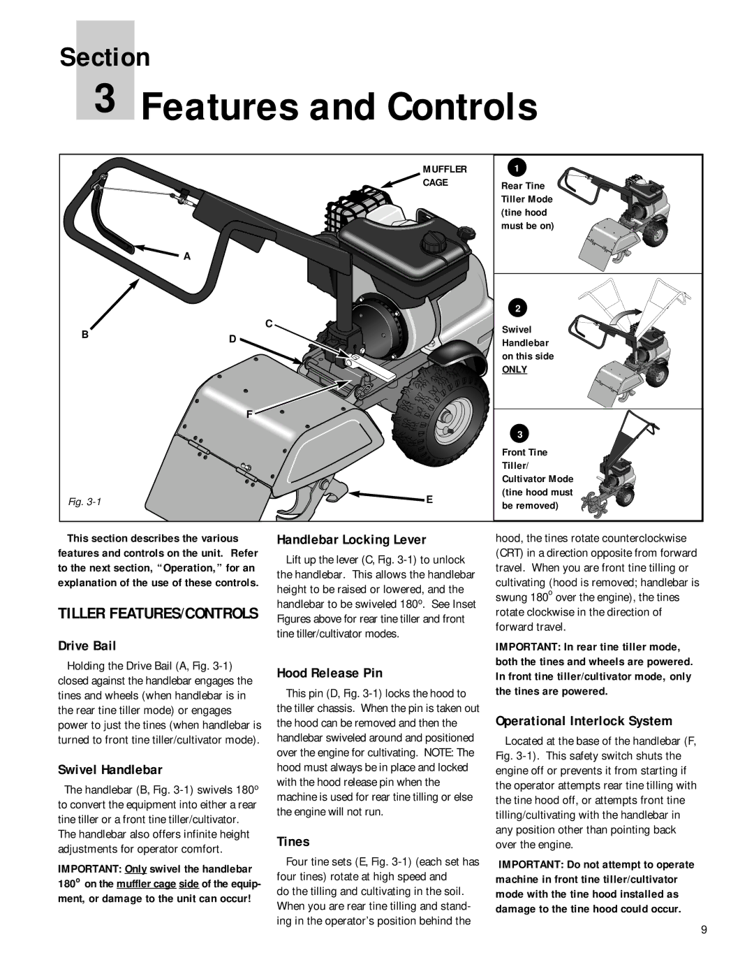
| MUFFLER | 1 | |
| CAGE | Rear Tine | |
|
| Tiller Mode | |
|
| (tine hood | |
|
| must be on) | |
| A |
| |
|
| 2 | |
B | C | Swivel | |
D | |||
Handlebar | |||
| |||
|
| on this side | |
|
| ONLY | |
| F |
| |
|
| 3 | |
|
| Front Tine | |
|
| Tiller/ | |
|
| Cultivator Mode | |
Fig. | E | (tine hood must | |
be removed) | |||
|
|
This section describes the various features and controls on the unit. Refer to the next section, “Operation,” for an explanation of the use of these controls.
TILLER FEATURES/CONTROLS
Drive Bail
Holding the Drive Bail (A, Fig.
Swivel Handlebar
The handlebar (B, Fig.
The handlebar also offers infinite height adjustments for operator comfort.
IMPORTANT: Only swivel the handlebar 180o on the muffler cage side of the equip- ment, or damage to the unit can occur!
Handlebar Locking Lever
Lift up the lever (C, Fig.
Hood Release Pin
This pin (D, Fig.
Tines
Four tine sets (E, Fig.
do the tilling and cultivating in the soil. When you are rear tine tilling and stand- ing in the operator’s position behind the
hood, the tines rotate counterclockwise (CRT) in a direction opposite from forward travel. When you are front tine tilling or cultivating (hood is removed; handlebar is swung 180o over the engine), the tines rotate clockwise in the direction of forward travel.
IMPORTANT: In rear tine tiller mode, both the tines and wheels are powered. In front tine tiller/cultivator mode, only the tines are powered.
Operational Interlock System
Located at the base of the handlebar (F, Fig.
IMPORTANT: Do not attempt to operate machine in front tine tiller/cultivator mode with the tine hood installed as damage to the tine hood could occur.
9