RZT 50 specifications
The Troy-Bilt RZT 50 is a notable addition to the riding mower market, designed to provide both power and precision for homeowners seeking a reliable solution for lawn care. With a cutting width of 50 inches, this zero-turn riding mower allows users to tackle larger areas efficiently, making it suitable for properties with expansive lawns.One of the standout features of the RZT 50 is its robust engine, typically powered by a 25 HP Briggs & Stratton engine. This engine delivers impressive torque and reliability, offering users the ability to handle tough mowing conditions without losing power. The mower's design prioritizes ease of use, with a trusty electric start that eliminates the hassle of manual cranking.
The RZT 50 is equipped with a dual hydrostatic drive system, which provides seamless steering and allows for easy maneuverability around obstacles such as trees, flower beds, and garden features. The zero-turn capability means that users can make tight turns without leaving uncut grass, giving the mower an edge in terms of efficiency and precision.
Another significant characteristic of the Troy-Bilt RZT 50 is its Comfort Seat, designed with ergonomics in mind. This padded, high-back seat offers support during longer mowing sessions, ensuring a comfortable riding experience. Additionally, the mower features adjustable cutting heights ranging from 1.5 inches to 4 inches, allowing users to customize their lawn care according to individual preferences and seasonal needs.
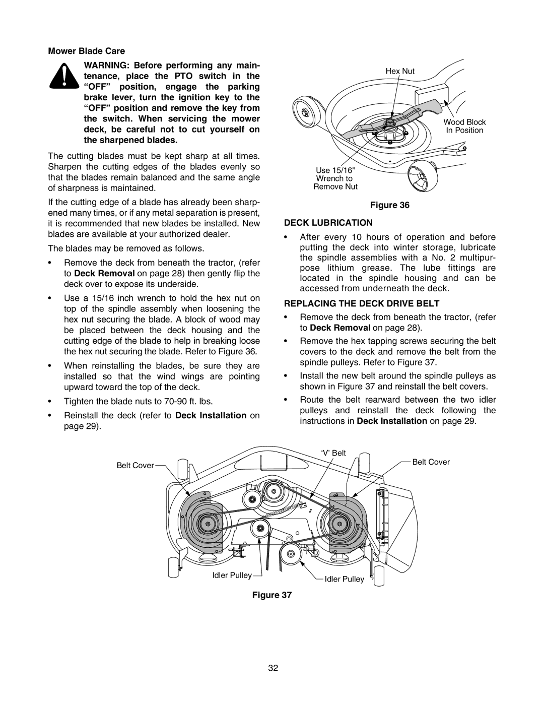
In terms of maintenance, the RZT 50 comes with a maintenance-free battery and easily accessible components for routine checks, reducing the downtime often associated with mower upkeep. Moreover, the mower boasts a durable steel frame and deck, ensuring longevity and resistance to wear over time.
Overall, the Troy-Bilt RZT 50 stands out with its combination of power, innovation, and user-friendly features, making it an ideal choice for homeowners aiming to maintain a lush and well-manicured lawn with minimal effort. With its thoughtfully designed capabilities, the RZT 50 proves that effective lawn care can be both easy and enjoyable.

