user manual
TA-500
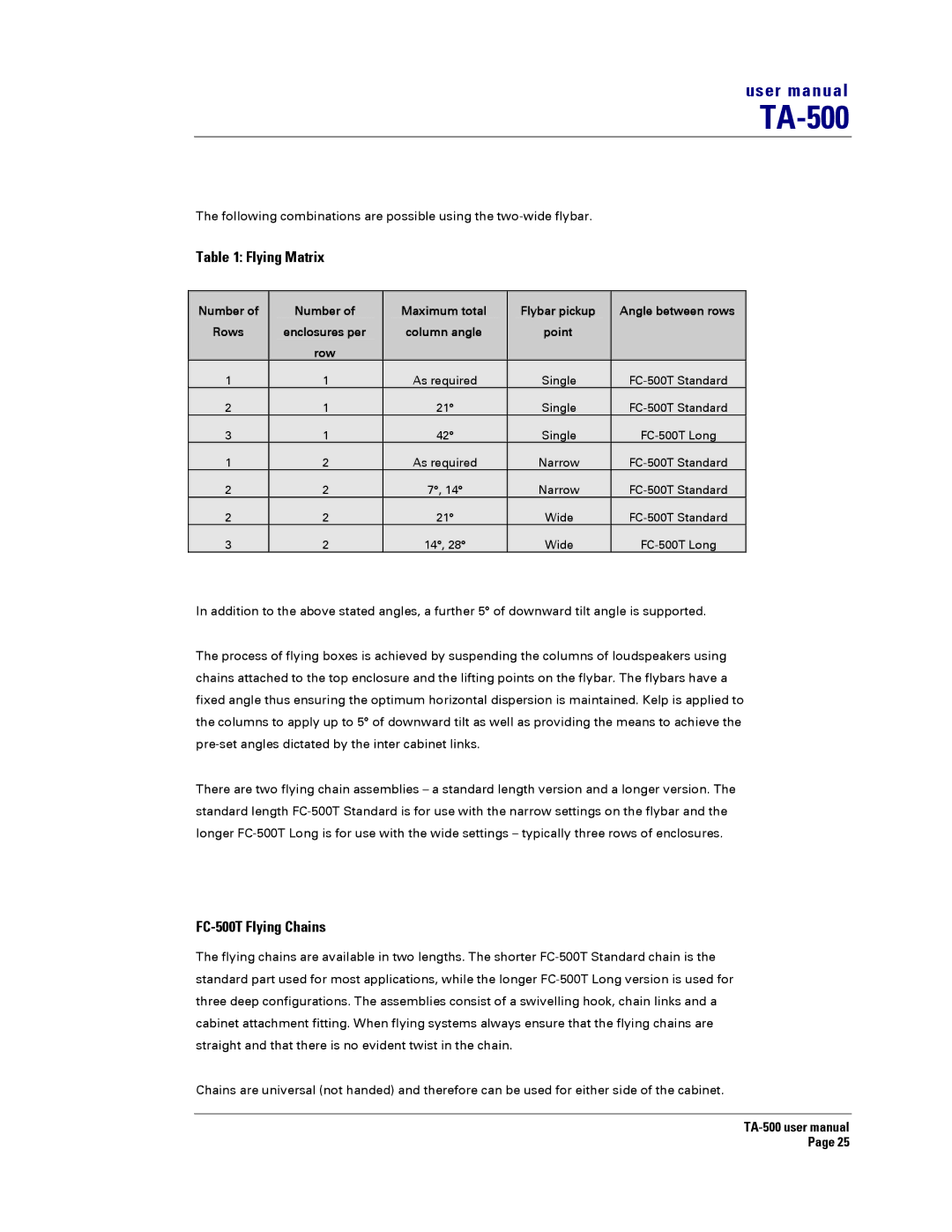
The following combinations are possible using the
Table 1: Flying Matrix
Number of | Number of | Maximum total | Flybar pickup |
| Angle between rows |
Rows | enclosures per | column angle | point |
|
|
| row |
|
|
|
|
1 | 1 | As required | Single |
| |
2 | 1 | 21° | Single |
| |
3 | 1 | 42° | Single |
| |
1 | 2 | As required | Narrow |
| |
2 | 2 | 7°, 14° | Narrow |
| |
2 | 2 | 21° | Wide |
| |
3 | 2 | 14°, 28° | Wide |
|
In addition to the above stated angles, a further 5° of downward tilt angle is supported.
The process of flying boxes is achieved by suspending the columns of loudspeakers using chains attached to the top enclosure and the lifting points on the flybar. The flybars have a fixed angle thus ensuring the optimum horizontal dispersion is maintained. Kelp is applied to the columns to apply up to 5° of downward tilt as well as providing the means to achieve the
There are two flying chain assemblies – a standard length version and a longer version. The standard length
FC-500T Flying Chains
The flying chains are available in two lengths. The shorter
Chains are universal (not handed) and therefore can be used for either side of the cabinet.
Page 25
