3.7.2 System Fan Layout
The following table provides the information for system fan layout.
System Fan Speed Control Signal
| M1210 Adapter Board | Connect to | Motherboard |
|
|
|
|
| J16 (PWM Signal) | Æ | J11 (PWM Signal) |
|
|
|
|
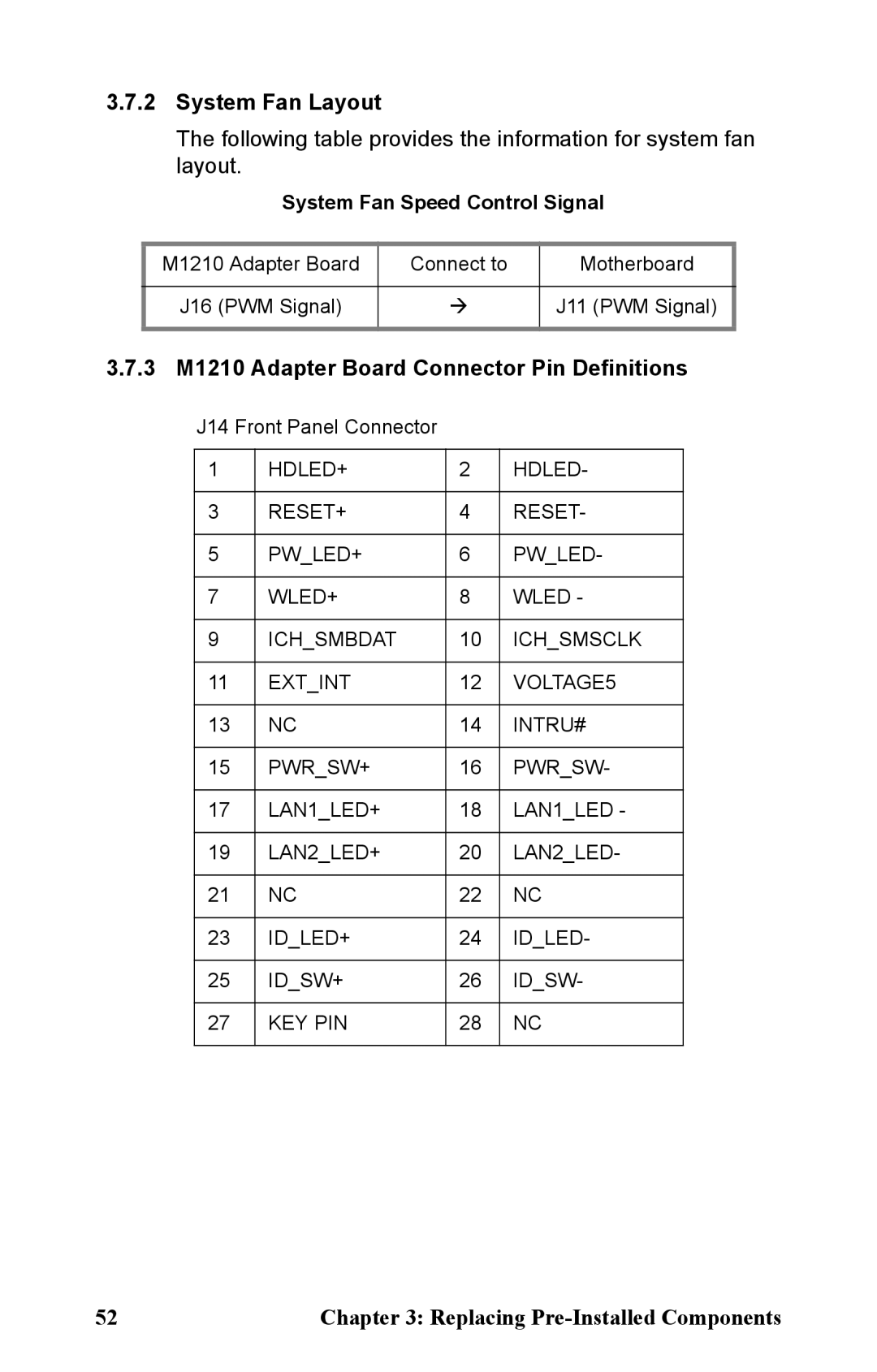
3.7.3 M1210 Adapter Board Connector Pin Definitions
J14 Front Panel Connector
1 | HDLED+ | 2 | HDLED- |
|
|
|
|
3 | RESET+ | 4 | RESET- |
|
|
|
|
5 | PW_LED+ | 6 | PW_LED- |
|
|
|
|
7 | WLED+ | 8 | WLED - |
|
|
|
|
9 | ICH_SMBDAT | 10 | ICH_SMSCLK |
|
|
|
|
11 | EXT_INT | 12 | VOLTAGE5 |
|
|
|
|
13 | NC | 14 | INTRU# |
|
|
|
|
15 | PWR_SW+ | 16 | PWR_SW- |
|
|
|
|
17 | LAN1_LED+ | 18 | LAN1_LED - |
|
|
|
|
19 | LAN2_LED+ | 20 | LAN2_LED- |
|
|
|
|
21 | NC | 22 | NC |
|
|
|
|
23 | ID_LED+ | 24 | ID_LED- |
|
|
|
|
25 | ID_SW+ | 26 | ID_SW- |
|
|
|
|
27 | KEY PIN | 28 | NC |
|
|
|
|
52 | Chapter 3: Replacing |