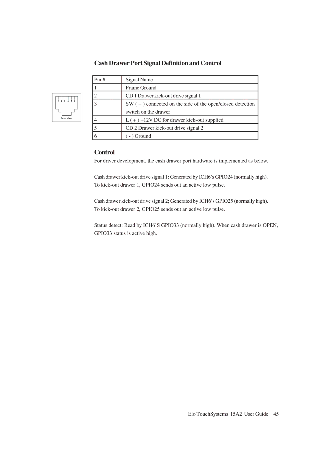
Cash Drawer Port Signal Definition and Control

Pin #

Signal Name

1Frame Ground

2CD 1 Drawer kick-out drive signal 1

3SW ( + ) connected on the side of the open/closed detection switch on the drawer

4L ( + ) +12V DC for drawer kick-out supplied

5CD 2 Drawer kick-out drive signal 2

6( - ) Ground

Control

For driver development, the cash drawer port hardware is implemented as below.

Cash drawer kick-out drive signal 1: Generated by ICH6’s GPIO24 (normally high). To kick-out drawer 1, GPIO24 sends out an active low pulse.

Cash drawer kick-out drive signal 2; Generated by ICH6’s GPIO25 (normally high). To kick-out drawer 2, GPIO25 sends out an active low pulse.

Status detect: Read by ICH6’S GPIO33 (normally high). When cash drawer is OPEN, GPIO33 status is active high.
Elo TouchSystems 15A2 User Guide 45

Page 45
Image 45
Tyco Electronics 15A2 15 LCD Multifuntion Touchcomputer, ESY15A2 manual Cash Drawer Port Signal Definition and Control