LOCATING THE HEATER | Notes |
AS A LOCATION IS SELECTED, KEEP THE FOLLOWING MIND: |
|
1.The chimney connection should be as airtight as possible. The heater must have its own chimney flue. Do not connect this unit to a chimney flue serving another appliance. If there is no chimney near where you wish to place the heater, you can use a UL 103HT Residential Type and Building Heating Ap- pliance Chimney.
2.Place the heater on solid masonry or solid concrete. When the heater is used on a combustible floor, use a
in./ft. 2 hr. Deg. F with
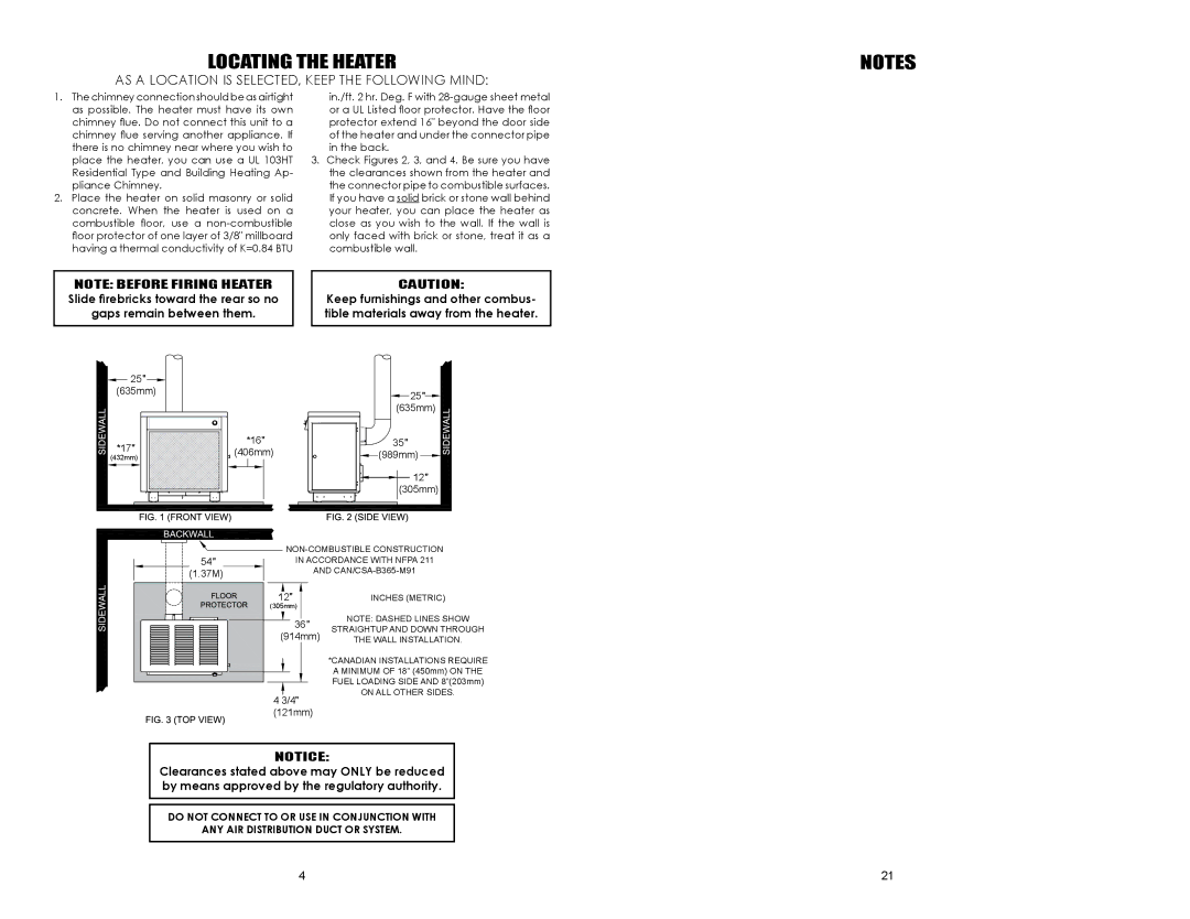
3.Check Figures 2, 3, and 4. Be sure you have the clearances shown from the heater and the connector pipe to combustible surfaces. If you have a solid brick or stone wall behind your heater, you can place the heater as close as you wish to the wall. If the wall is only faced with brick or stone, treat it as a combustible wall.
NOTE: BEFORE FIRING HEATER Slide firebricks toward the rear so no gaps remain between them.
CAUTION:
Keep furnishings and other combus- tible materials away from the heater.
![]() 25
25![]()
![]() (635mm)
(635mm)
*17![]()
(432mm)
*16 (406mm)
 25
25
 (635mm)
![]()
![]()
![]() 35
35![]()
 (989mm)


 12
12 (305mm)
54 | IN ACCORDANCE WITH NFPA 211 | ||
(1.37M) | AND | ||
12 |
| INCHES (METRIC) | |
(305mm) |
| ||
| 36 | NOTE: DASHED LINES SHOW | |
| STRAIGHTUP AND DOWN THROUGH | ||
(914mm) | |||
THE WALL INSTALLATION. | |||
|
| *CANADIAN INSTALLATIONS REQUIRE | |
|
| A MINIMUM OF 18” (450mm) ON THE | |
|
| FUEL LOADING SIDE AND 8”(203mm) | |
4 3/4 | ON ALL OTHER SIDES. | ||
| |||
(121mm) |
| ||
Notice:
Clearances stated above may ONLY be reduced by means approved by the regulatory authority.
DO NOT CONNECT TO or use in conjunction with
ANY AIR DISTRIBUTION DUCT OR SYSTEM.
4 | 21 |