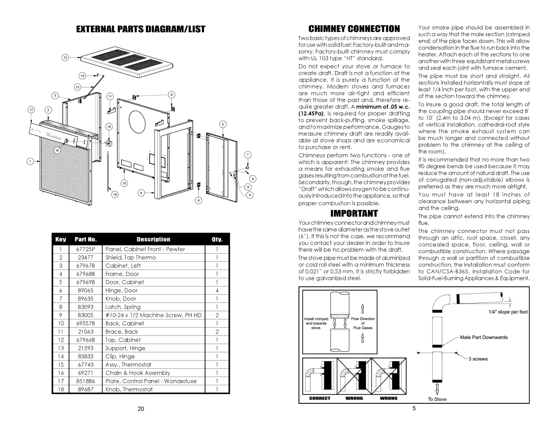
External Parts Diagram/List
CHIMNEY CONNECTION
Your smoke pipe should be assembled in such a way that the male section (crimped
17
1
12
14
13
3
2
18
11
15
10
164
6
5
6
7
9
8
9
Two basic types of chimneys are approved for use with solid fuel:
Do not expect your stove or furnace to create draft. Draft is not a function of the appliance. It is purely a function of the chimney. Modern stoves and furnaces are much more
Chimneys perform two functions - one of which is apparent: The chimney provides a means for exhausting smoke and flue gases resulting from combustion of the fuel. Secondarily, though, the chimney provides “Draft” which allows oxygen to be continu- ously introduced into the appliance, so that proper combustion is possible.
IMPORTANT
end) of the pipe faces down. This will allow condensation in the flue to run back into the heater. Attach each of the sections to one another with three equidistant metal screws and seal each joint with furnace cement.
The pipe must be short and straight. All sections installed horizontally must slope at least 1/4 inch per foot, with the upper end of the section toward the chimney.
To insure a good draft, the total length of the coupling pipe should never exceed 8’ to 10’ (2.4m to 3.04 m). (Except for cases of vertical installation,
It is recommended that no more than two 90 degree bends be used because it may reduce the amount of natural draft. The use of corrugated
You must have at least 18 inches of clearance between any horizontal piping and the ceiling.
The pipe cannot extend into the chimney
Key | Part No. | Description | Qty. |
|
|
|
|
1 | 67725P | Panel, Cabinet Front - Pewter | 1 |
2 | 23477 | Shield, Top Thermo | 1 |
3 | 67967B | Cabinet, Left | 1 |
4 | 67968B | Frame, Door | 1 |
5 | 67969B | Door, Cabinet | 1 |
Your chimney connector and chimney must have the same diameter as the stove outlet (6”). If this is not the case, we recommend you contact your dealer in order to insure there will be no problem with the draft.
The stove pipe must be made of aluminized or cold roll steel with a minimum thickness of 0.021” or 0.53 mm. It is strictly forbidden to use galvanized steel.
flue.
The chimney connector must not pass through an attic, roof space, closet, any concealed space, floor, ceiling, wall or combustible construction. Where passage through a wall or partition of combustible construction, the installation must conform to
6 | 89065 | Hinge, Door | 4 |
7 | 89635 | Knob, Door | 1 |
8 | 83093 | Latch, Spring | 1 |
9 | 83005 | 2 | |
10 | 69557B | Back, Cabinet | 1 |
11 | 21063 | Brace, Back | 2 |
12 | 67966B | Top, Cabinet | 1 |
13 | 21593 | Support, Hinge | 1 |
14 | 83833 | Clip, Hinge | 1 |
15 | 67743 | Assy., Thermostat | 1 |
16 | 69271 | Chain & Hook Assembly | 1 |
17 | 851886 | Plate, Control Panel - Wonderluxe | 1 |
18 | 89687 | Knob, Thermostat | 1 |
|
| 20 |
|
To Stove |
5 |