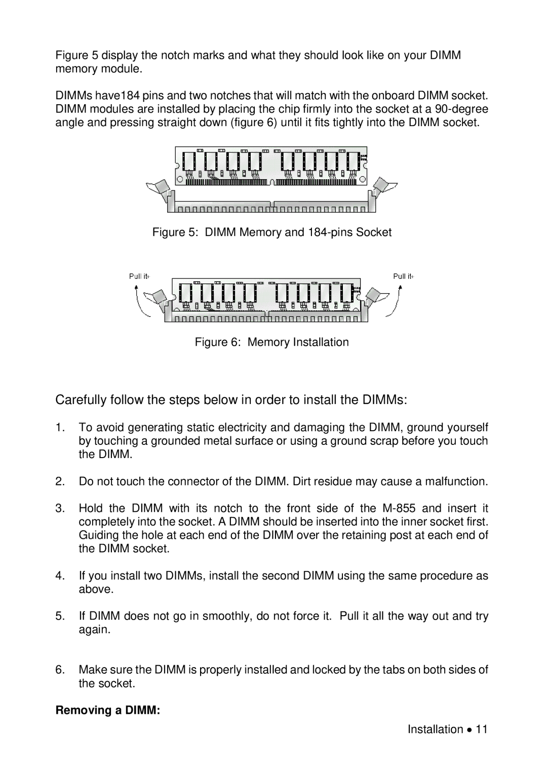
Figure 5 display the notch marks and what they should look like on your DIMM memory module.
DIMMs have184 pins and two notches that will match with the onboard DIMM socket. DIMM modules are installed by placing the chip firmly into the socket at a
Figure 5: DIMM Memory and 184-pins Socket
Figure 6: Memory Installation
Carefully follow the steps below in order to install the DIMMs:
1.To avoid generating static electricity and damaging the DIMM, ground yourself by touching a grounded metal surface or using a ground scrap before you touch the DIMM.
2.Do not touch the connector of the DIMM. Dirt residue may cause a malfunction.
3.Hold the DIMM with its notch to the front side of the
4.If you install two DIMMs, install the second DIMM using the same procedure as above.
5.If DIMM does not go in smoothly, do not force it. Pull it all the way out and try again.
6.Make sure the DIMM is properly installed and locked by the tabs on both sides of the socket.
Removing a DIMM:
Installation • 11