Manuals
/
Vermont Casting
/
Household Appliance
/
Indoor Fireplace
Vermont Casting
3030 Assembly Procedures, Unpack the Firebox, Shell / Firebox Assembly, 20005004
Models:
3030
3031
3032
3033
1
9
26
26
Download
26 pages
62.24 Kb
6
7
8
9
10
11
12
13
Troubleshooting
Specification
Flame Characteristics
Install
Warranty
Dimension
Maintenance
Optional Accessories Available
Assembly Procedures
Clean the Combustor Module
Page 9
Image 9
Page 8
Page 10
Page 9
Image 9
Page 8
Page 10
Contents
WHATTO DO IF YOU SMELL GAS
Homeowner’s Installation
Do not try to light any appli- ance
INSTALLER / CONSUMER SAFETY INFORMATION
Table Of Contents
Vermont Castings UVS27 Vent-FreeGas Heater
20005004
Installation & Operating Instructions
Vermont Castings UVS27 Vent-FreeGas Heater
20005004
Vermont Castings UVS27 Vent-FreeGas Heater
Shell Dimensions
20005004
Freestanding Stove
Minimum Clearances to Combustible Materials
Clearance Requirements
Hearth Requirements
Vermont Castings UVS27 Vent-FreeGas Heater
Gas Inlet and Manifold Pressures
Gas Specifications
UVS27R & UVS27M Vent-Free Certified to
ANSI Z21.11.2a-2001 Unvented Heaters
Fresh Air Requirements for Combustion
Vent Free Features
and Ventilation
Provide For Adequate Ventilation
Vermont Castings UVS27 Vent-FreeGas Heater
W A R N I N G
W A R N I N G
20005004
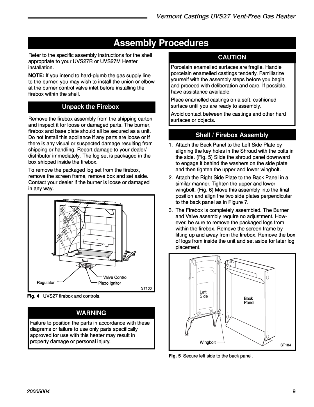
Shell / Firebox Assembly
Assembly Procedures
Unpack the Firebox
Vermont Castings UVS27 Vent-FreeGas Heater
Install Optional Fan Kit
Vermont Castings UVS27 Vent-FreeGas Heater
20005004
Install ON/OFF Switch
Vermont Castings UVS27 Vent-FreeGas Heater
20005004
Thermostat Connection Optional
Glass & Catalyst Installation
Vermont Castings UVS27 Vent-FreeGas Heater
20005004
Connect the Gas Supply Line
Vermont Castings UVS27 Vent-FreeGas Heater
20005004
Install Log Set
Vermont Castings UVS27 Vent-FreeGas Heater
20005004
Complete the Installation
Vermont Castings UVS27 Vent-FreeGas Heater
20005004
Flame Characteristics
Flame & Temperature Adjustment
Operation
Your First Fire
Lighting and Operating Instructions
FOR YOUR SAFETY READ BEFORE LIGHTING
Lighting Instructions
To Turn Off Gas To Heater
CONDITION
Troubleshooting
POSSIBLE CAUSE
Vermont Castings UVS27 Vent-FreeGas Heater
Vermont Castings UVS27 Vent-FreeGas Heater
Troubleshooting cont’d
CONDITION
POSSIBLE CAUSE
Firebox Cleaning and Inspection
Maintenance
Cleaning Procedure
Glass Replacement
Catalytic Combustor
Clean the Combustor Module
Remove the Combustor Module
Replace The Combustor Module
UVS27R, UVS27M Vent Free Gas Heaters
Models
Vermont Castings UVS27 Vent-FreeGas Heater
20005004
Models 3030, 3031, 3032, 3033 continued
UVS27R, UVS27M Vent Free Gas Heaters
Vermont Castings UVS27 Vent-FreeGas Heater
20005004
Vermont Castings UVS27 Vent-FreeGas Heater
UVS27R, UVS27M Vent Free Gas Heaters
Models 3030, 3031, 3032, 3033 continued
Shell Enamel Part Numbers - Hearthmount
Remote Controls
Optional Accessories Available
Fan Kits
Glass / Catalyst Kit UVGODCFK
PRODUCT COVERED BY THIS WARRANTY
LIMITED LIFETIME WARRANTY
IF WARRANTY SERVICE IS NEEDED…
Vermont Castings UVS27 Vent-FreeGas Heater
Top
Page
Image
Contents