WinterWarm Fireplace Insert or System specifications
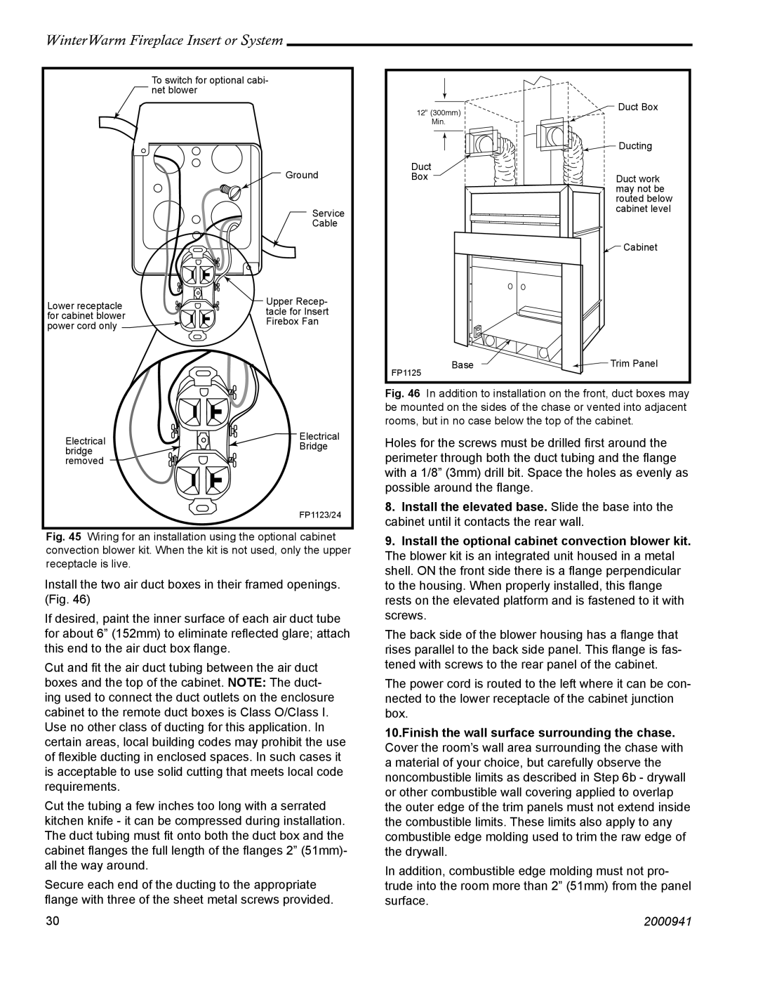
The Vermont Casting WinterWarm fireplace insert is a remarkable addition to any home, delivering both efficiency and elegance to your living space. Designed to enhance heat delivery and overall ambiance, this insert is a popular choice among homeowners looking to create a warm and inviting atmosphere during the colder months.One of the standout features of the WinterWarm insert is its efficient heating capability. With a remarkable heating capacity that can warm up to 2,000 square feet, this system transforms your drafty fireplace into a powerful heat source. The efficient design maximizes heat output while minimizing the amount of wood needed, ensuring you stay warm without emptying your wallet on heating costs.
The insert also incorporates advanced technology that promotes cleaner burning and reduced emissions. With its secondary combustion system, the WinterWarm optimizes the burn process, allowing for improved heat production and cleaner air. This feature not only benefits the environment but also extends the life of the unit, making it a sustainable choice for homeowners.
Aesthetically, the Vermont Casting WinterWarm insert doesn’t compromise on style. It is available in various finishes, including classic black and elegant enamel options, allowing homeowners to choose a unit that seamlessly blends with their home decor. The large viewing window provides a lovely view of the flames, enhancing the cozy feel of your room while adding a touch of sophistication.
The construction of the WinterWarm insert is another highlight. Made from durable cast iron, this unit is built to last, ensuring that it will provide warmth and comfort for many winters to come. The cast iron not only offers exceptional heat retention but also contributes to the timeless charm of the insert.
Additionally, the WinterWarm insert features an easy-to-use air control system, allowing you to adjust the burn rate and heat output quickly. This user-friendly design makes it accessible for everyone, whether you are a seasoned wood-burning enthusiast or new to the experience.
In summary, the Vermont Casting WinterWarm fireplace insert is an outstanding option for those looking to combine efficiency with style. With its powerful heating capabilities, advanced combustion technology, and elegant design, it transforms any standard fireplace into the heart of your home during winter months. This fireplace insert not only enhances indoor comfort but also adds a timeless element to your living space, making it a worthwhile investment for homeowners.

