using the gas cooktop
GAS BURNERS
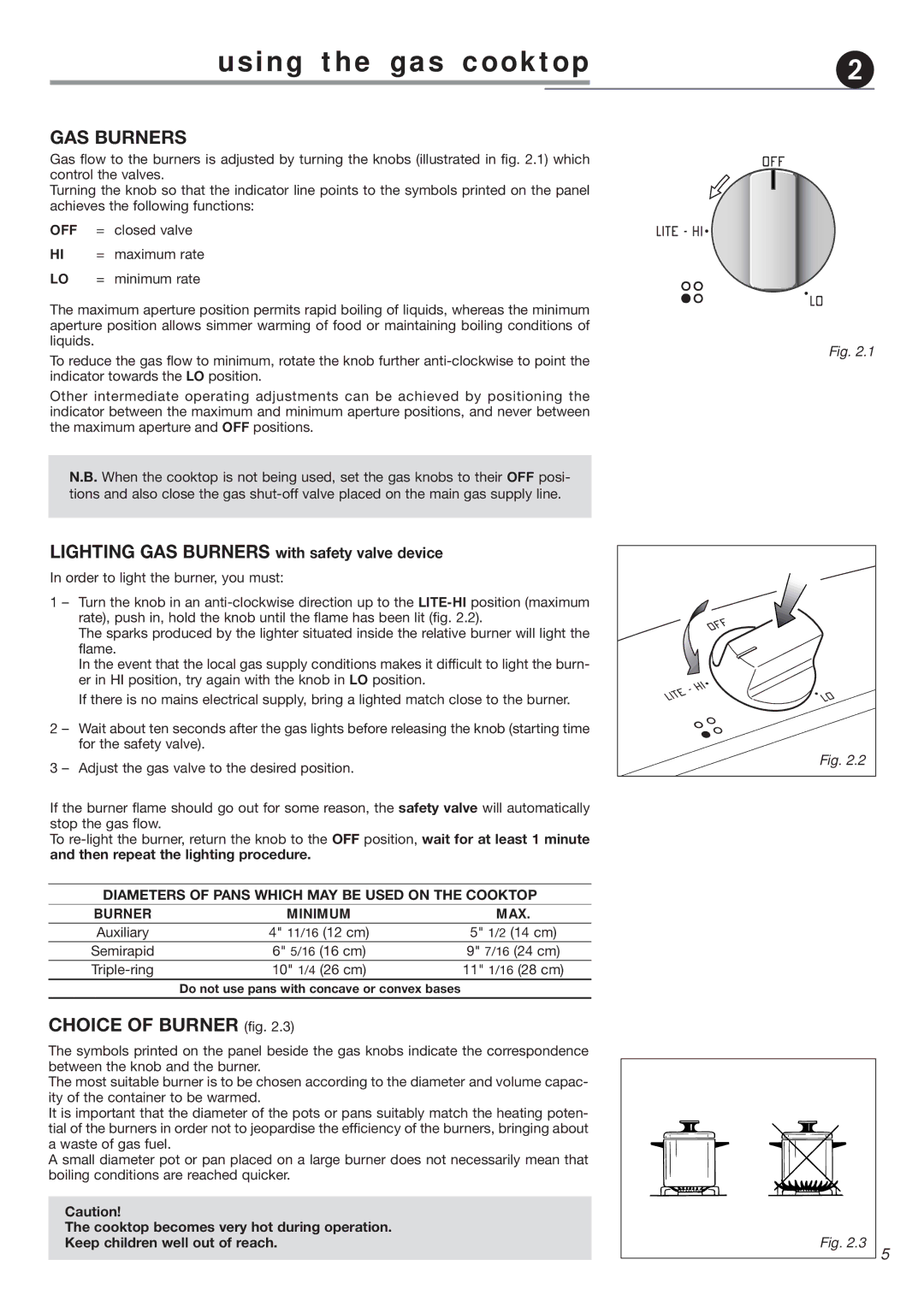
Gas flow to the burners is adjusted by turning the knobs (illustrated in fig. 2.1) which control the valves.
Turning the knob so that the indicator line points to the symbols printed on the panel achieves the following functions:
OFF = closed valve
HI = maximum rate
LO = minimum rate
The maximum aperture position permits rapid boiling of liquids, whereas the minimum aperture position allows simmer warming of food or maintaining boiling conditions of liquids.
To reduce the gas flow to minimum, rotate the knob further
Other intermediate operating adjustments can be achieved by positioning the indicator between the maximum and minimum aperture positions, and never between the maximum aperture and OFF positions.
N.B. When the cooktop is not being used, set the gas knobs to their OFF posi- tions and also close the gas
LIGHTING GAS BURNERS with safety valve device
In order to light the burner, you must:
1 – Turn the knob in an
The sparks produced by the lighter situated inside the relative burner will light the flame.
In the event that the local gas supply conditions makes it difficult to light the burn- er in HI position, try again with the knob in LO position.
If there is no mains electrical supply, bring a lighted match close to the burner.
2 – Wait about ten seconds after the gas lights before releasing the knob (starting time for the safety valve).
3 – Adjust the gas valve to the desired position.
If the burner flame should go out for some reason, the safety valve will automatically stop the gas flow.
To
DIAMETERS OF PANS WHICH MAY BE USED ON THE COOKTOP
BURNER | MINIMUM | MAX. |
Auxiliary | 4" 11/16 (12 cm) | 5" 1/2 (14 cm) |
Semirapid | 6" 5/16 (16 cm) | 9" 7/16 (24 cm) |
10" 1/4 (26 cm) | 11" 1/16 (28 cm) | |
| Do not use pans with concave or convex bases |
|
|
|
|
CHOICE OF BURNER (fig. 2.3)
The symbols printed on the panel beside the gas knobs indicate the correspondence between the knob and the burner.
The most suitable burner is to be chosen according to the diameter and volume capac- ity of the container to be warmed.
It is important that the diameter of the pots or pans suitably match the heating poten- tial of the burners in order not to jeopardise the efficiency of the burners, bringing about a waste of gas fuel.
A small diameter pot or pan placed on a large burner does not necessarily mean that boiling conditions are reached quicker.
Caution!
The cooktop becomes very hot during operation.
Keep children well out of reach.
Fig. 2.1
Fig. 2.2
Fig. 2.3
5