LP/Propane Tank Connection
Outdoor side burners orificed for use with LP/Propane gas come equipped with a high capacity hose/regulator assembly for connection to a standard 20 lb. LP/Propane cylinder equipped with a Type 1,
Connection: 1/2” (1.3 cm) NPT male with a 3/8” (.95) flare adapter
Operating Pressure: 10.0” W.C.P.
To connect to LP/Propane regulator/hose assembly:
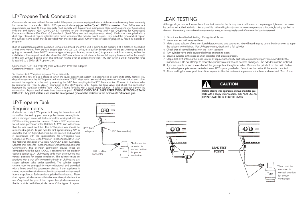
Although the flow of gas is stopped when the quick disconnect system is disconnected as part of its safety feature, you should always turn the LP/Propane tank main valve “OFF” after each use and during transport of the tank or unit. First connect the regulator to the unit by screwing the 3/8” flare coupling to the 3/8” flare adapter. Connect to the tank valve by screwing the Type 1,
CHANGE. Any joint sealant used must be an approved type and be resistive to the actions of LP/Propane gas.
LEAK TESTING
Although all gas connections on the unit are leak tested at the factory prior to shipment, a complete gas tightness check must be performed at the installation due to possible mishandling in shipment or excessive pressure unknowingly being applied to the unit. Periodically check the whole system for leaks, or immediately check if the smell of gas is detected.
1. Do not smoke while leak testing. Extinguish all flames.
2.Never leak test with an open flame.
3.Make a soap solution of one part liquid detergent and one part water. You will need a spray bottle, brush or towel to apply the solution to the fittings. For LP/Propane units, check with a full cylinder.
4.Check that all control knobs are in the “OFF” position.
5.Turn cylinder valve knob counter clockwise one turn to open.
6.Blowing bubbles in the soap solution indicates that a leak is present.
7.Stop a leak by tightening the loose joint or by replacing the faulty part with a replacement part recommended by the manufacturer. Do not attempt to repair the cylinder valve if it should become damaged. The cylinder must be replaced.
8.If you are unable to stop a leak, shut off the gas supply at the cylinder valve. Remove the cylinder from the unit. Call an authorized gas appliance service technician or LP/Propane gas dealer. Do not use the unit until the leak is corrected.
9.After checking for leaks, push in and turn any control knob to release the pressure in the hose and manifold. Turn off the
CAUTION
Before placing into operation, always check for gas leaks with a soapy water solution. DO NOT USE AN OPEN FLAME TO CHECK FOR LEAKS!
LP/Propane Tank
Requirements
A dented or rusty LP/Propane tank may be hazardous and should be checked by your tank supplier. Never use a cylinder with a damaged valve. All tanks should be equipped with an OPD (overfilling protection device). This is a DOT requirement for all tanks purchased after October 1, 1998 and will ensure that the tank is not overfilled. The LP/Propane tank should be a standard
3/8” flare | 3/8” flare coupling |
adaptor |
|
|
|
| *Tank must be |
|
|
|
| mounted in |
|
|
|
| vertical position |
|
| Tank | ||
Type 1, |
| |||
|
| for proper | ||
connector |
|
|
| |
|
|
| ventilation | |
|
|
|
| |
|
|
|
|
|
|
|
|
|
|
LEAK TEST
POINTS
Tank
*Tank must be mounted in vertical position for proper ventilation
6 | 7 |