VENTILATION FOR BUILT-IN INSTALLATIONS
Not less than 5.00 inches from inside bottom of countertop.
5.00 inch maximum
Vents
BURNER ADJUSTMENT– VGSB5152
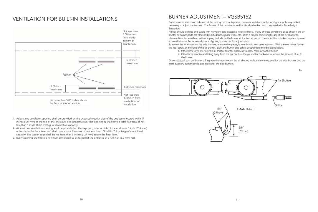
Each burner is tested and adjusted at the factory prior to shipment; however, variations in the local gas supply may make it necessary to adjust the burners. The flames of the burners should be visually checked and compared with flame height illustration.
Flames should be blue and stable with no yellow tips, excessive noise or lifting. If any of these conditions exist, check if the air shutter or burner ports are blocked by dirt, debris, spider webs, etc. With a proper flame height, adjust the air shutter to obtain a blue flame with no yellow tipping that sits on the burner at the burner ports. The air shutter is locked in place by a set screw which must be loosened prior to lighting the burner for adjustments.
To access the air shutter on the side burners, remove the grates, burner bowls, and grate support. With a screw driver, loosen the
1.If the flame is yellow, turn the air shutter counter clockwise to allow more air to the burner.
2.If the flame is noisy and lifting away from the burner, turn the air shutter clockwise to reduce the amount of air to the burner.
Once adjusted, turn the burner off, tighten the set screw on the air shutter, replace the valve panel for the side burners and the grate support, burner bowls, and grates for the side burners.
To
 Air Shutters
5.00inch maximum
No more than 5.00 inches above the floor of the installation.
1.00 inch maximum
Not less than
1.00inch from inside floor of installation.
Orifice
1½” |
| FLAME HEIGHT |
(3.8 cm) |
|
|
|
| |
|
|
|
1.At least one ventilation opening shall be provided on the exposed exterior side of the enclosure located within 5 inches (127 mm) of the top of the enclosure and unobstructed. The opening(s) shall have a total free area of not less than 1 in2/lb (14.2 cm2/kg) of stored fuel capacity.
2.At least one ventilation opening shall be provided on the exposed, exterior side of the enclosure 1 inch (25.4 mm) or less from the floor level and shall have a total free area of not less than 1/2 in2/lb (7.1 cm2/kg) of stored fuel capacity. The upper edge shall be no more than 5 inches (127 mm) above the floor level.
3.Every opening shall have a minimum dimension so as to permit the entrance of a 1/8 inch (3.2 mm) rod.
3/8” (.95 cm)
10 | 11 |