S T E P 5 | B L A C K B A G |
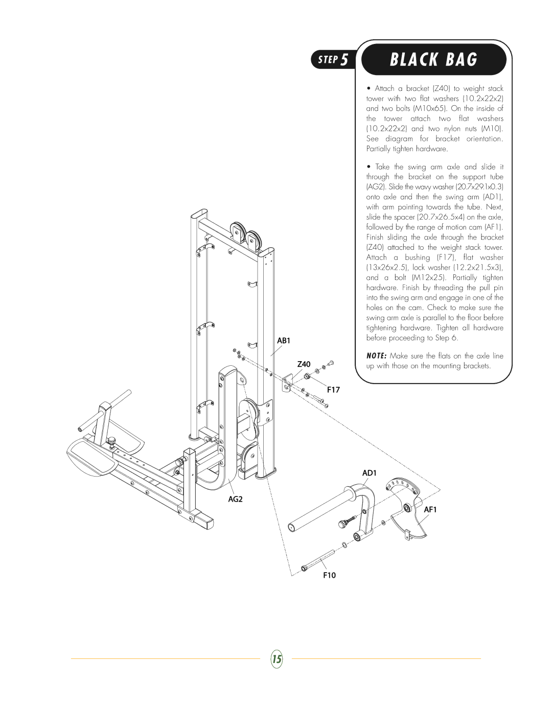
| • Attach a bracket (Z40) to weight stack |
| tower with two flat washers (10.2x22x2) |
| and two bolts (M10x65). On the inside of |
| the tower attach two flat washers |
| (10.2x22x2) and two nylon nuts (M10). |
| See diagram for bracket orientation. |
| Partially tighten hardware. |
| • Take the swing arm axle and slide it |
| through the bracket on the support tube |
| (AG2). Slide the wavy washer (20.7x29.1x0.3) |
| onto axle and then the swing arm (AD1), |
| with arm pointing towards the tube. Next, |
| slide the spacer (20.7x26.5x4) on the axle, |
| followed by the range of motion cam (AF1). |
| Finish sliding the axle through the bracket |
| (Z40) attached to the weight stack tower. |
| Attach a bushing (F17), flat washer |
| (13x26x2.5), lock washer (12.2x21.5x3), |
| and a bolt (M12x25). Partially tighten |
| hardware. Finish by threading the pull pin |
| into the swing arm and engage in one of the |
| holes on the cam. Check to make sure the |
| swing arm axle is parallel to the floor before |
| tightening hardware. Tighten all hardware |
AB1 | before proceeding to Step 6. |
| |
Z40 | N O T E : Make sure the flats on the axle line |
up with those on the mounting brackets. |
F17
AD1
AG2
AF1
F10
15
