| S T E P 2 | BLUE BAG |
|
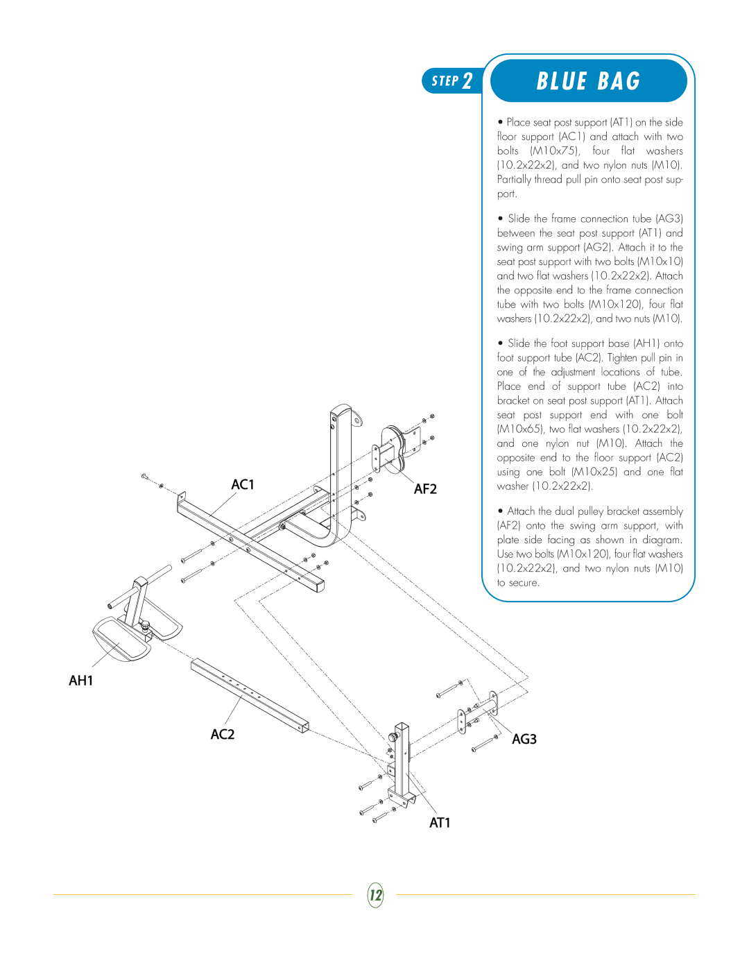
| • Place seat post support (AT1) on the side |
|
| floor support (AC1) and attach with two |
|
| bolts (M10x75), four flat washers |
|
| (10.2x22x2), and two nylon nuts (M10). |
|
| Partially thread pull pin onto seat post sup- |
|
| port. |
|
| • Slide the frame connection tube (AG3) |
|
| between the seat post support (AT1) and |
|
| swing arm support (AG2). Attach it to the |
|
| seat post support with two bolts (M10x10) |
|
| and two flat washers (10.2x22x2). Attach |
|
| the opposite end to the frame connection |
|
| tube with two bolts (M10x120), four flat |
|
| washers (10.2x22x2), and two nuts (M10). |
|
| • Slide the foot support base (AH1) onto |
|
| foot support tube (AC2). Tighten pull pin in |
|
| one of the adjustment locations of tube. |
|
| Place end of support tube (AC2) into |
|
| bracket on seat post support (AT1). Attach |
|
| seat post support end with one bolt |
|
| (M10x65), two flat washers (10.2x22x2), |
|
| and one nylon nut (M10). Attach the |
|
| opposite end to the floor support (AC2) |
AC1 |
| using one bolt (M10x25) and one flat |
AF2 | washer (10.2x22x2). | |
|
| |
|
| • Attach the dual pulley bracket assembly |
|
| (AF2) onto the swing arm support, with |
|
| plate side facing as shown in diagram. |
|
| Use two bolts (M10x120), four flat washers |
|
| (10.2x22x2), and two nylon nuts (M10) |
|
| to secure. |
AH1
AC2 | AG3 |
|
AT1
12
