VIVOTEK
Physical Description
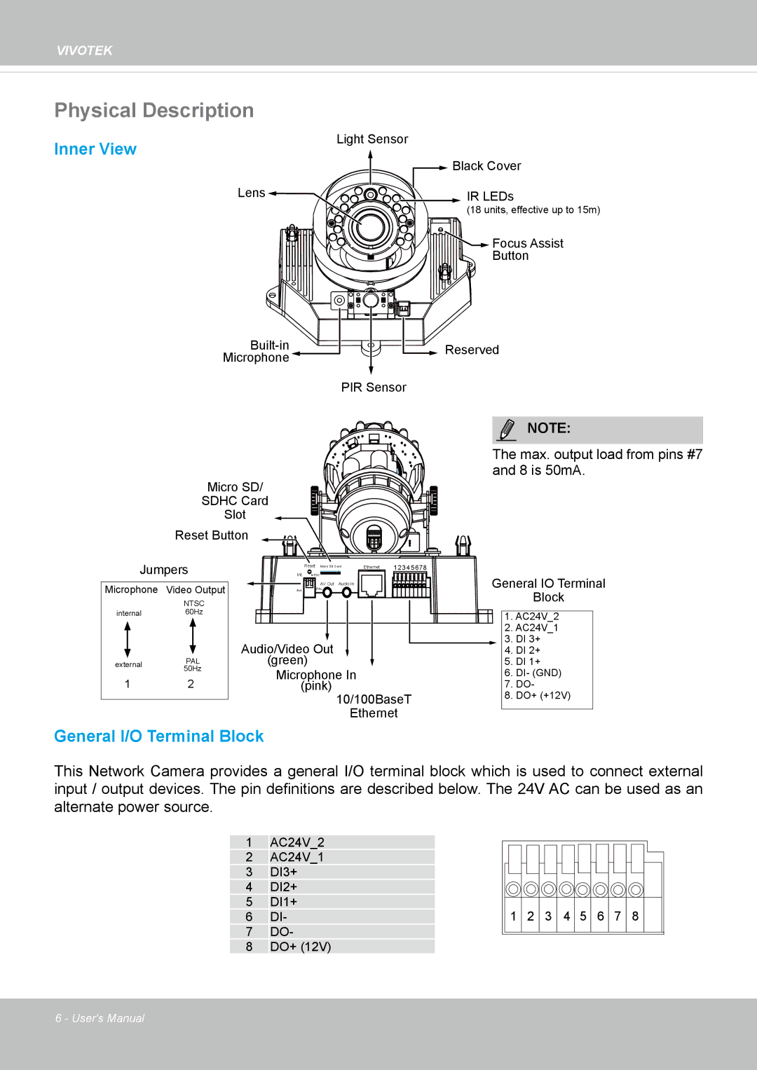
Inner View
Light Sensor
![]() Black Cover
Black Cover
Lens | IR LEDs |
(18 units, effective up to 15m)
Focus Assist
Button
![]()
![]()
![]()
![]()
![]() Reserved
Reserved
Microphone
PIR Sensor
Micro SD/
SDHC Card
Slot
Reset Button
NOTE:
The max. output load from pins #7 and 8 is 50mA.
Jumpers
Microphone Video Output
|
| NTSC | ||
internal | 60Hz | |||
|
|
|
| |
|
|
|
| |
external | PAL | |||
50Hz | ||||
|
| |||
1 2
| Reset Micro SD Card | Ethernet | 1234 5 678 |
Int. NTSC |
|
| |
| AV Out Audio In |
|
|
Ext. | PAL |
|
|
|
|
| |
Audio/Video Out
(green)
Microphone In
(pink)
10/100BaseT
Ethernet
General IO Terminal
Block
1.AC24V_2
2.AC24V_1
3.DI 3+
4.DI 2+
5.DI 1+
6.DI- (GND)
7.DO-
8.DO+ (+12V)
General I/O Terminal Block
This Network Camera provides a general I/O terminal block which is used to connect external input / output devices. The pin definitions are described below. The 24V AC can be used as an alternate power source.
1AC24V_2
2AC24V_1
3DI3+
4DI2+
5DI1+
6DI-
7DO-
8DO+ (12V)
1 2 3 4 5 6 7 8
6 - User's Manual