VIVOTEK
Network Deployment
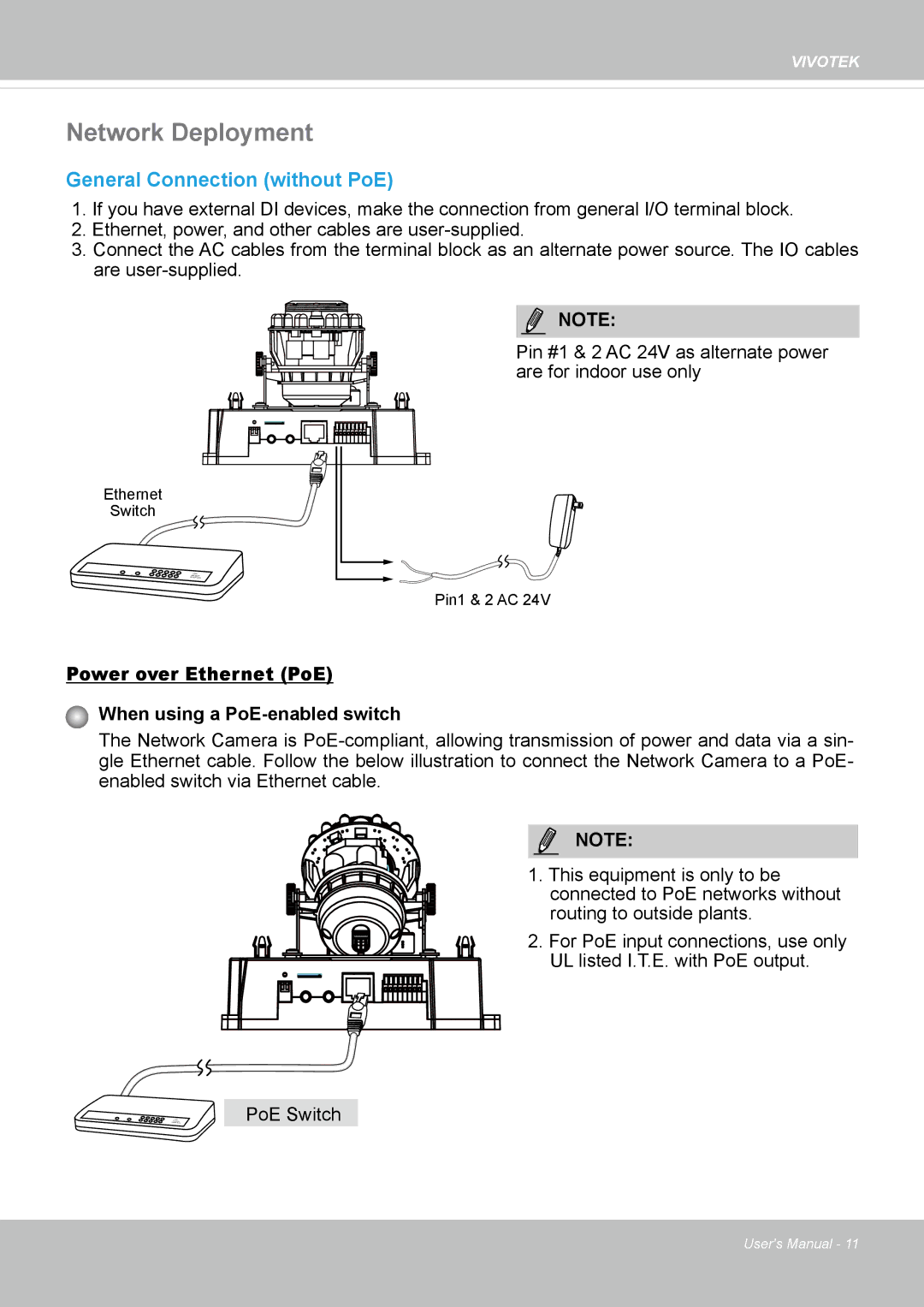
General Connection (without PoE)
1.If you have external DI devices, make the connection from general I/O terminal block.
2.Ethernet, power, and other cables are
3.Connect the AC cables from the terminal block as an alternate power source. The IO cables are
NOTE:
Pin #1 & 2 AC 24V as alternate power are for indoor use only
Ethernet
Switch
POWER | COLLISION | 1 |
|
|
|
| LINK |
|
|
|
|
| RECEIVE | ||
|
|
| 2 | 3 | 4 | 5 | PARTITION |
Pin1 & 2 AC 24V
Power over Ethernet (PoE)
When using a PoE-enabled switch
The Network Camera is
enabled switch via Ethernet cable.
NOTE:
1. This equipment is only to be connected to PoE networks without routing to outside plants.
2. For PoE input connections, use only UL listed I.T.E. with PoE output.
PoE Switch
User's Manual - 11