VIVOTEK
Network Deployment
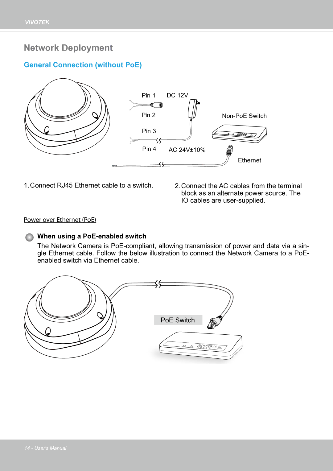
General Connection (without PoE)
Pin 1 | DC 12V |
Pin 2 | |
Pin 3 |
|
Pin 4 | AC 24V±10% |
| Ethernet |
1. Connect RJ45 Ethernet cable to a switch.
Power over Ethernet (PoE)
2.Connect the AC cables from the terminal block as an alternate power source. The IO cables are
When using a PoE-enabled switch
The Network Camera is
PoE Switch
POWER | COLLISION |
|
|
|
|
|
|
| 1 | 2 | 3 | 4 | 5 |
![]()
![]()
![]() LINK
LINK ![]() RECEIVE
RECEIVE ![]()
![]() PARTITION
PARTITION
14 - User's Manual