Installation
In this manual, "User" refers to whoever has access to the Network Camera, and "Administrator" refers to the person who can configure the Network Camera and grant user access to the camera.
Hardware installation
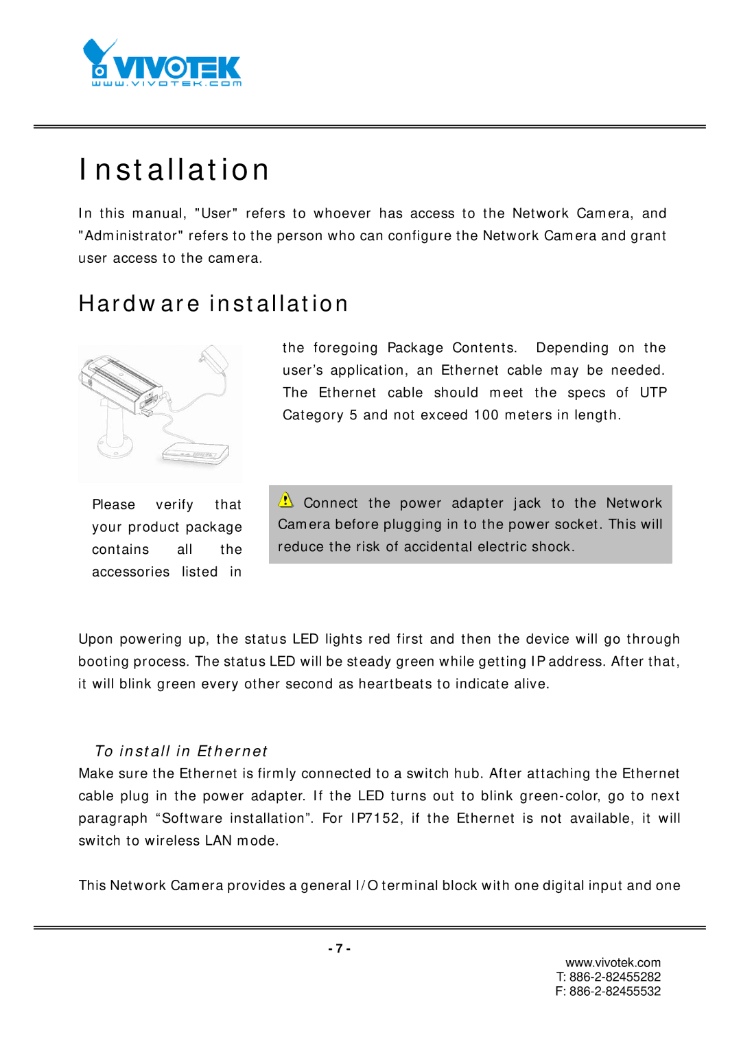
Please verify that your product package contains all the accessories listed in
the foregoing Package Contents. Depending on the user’s application, an Ethernet cable may be needed. The Ethernet cable should meet the specs of UTP Category 5 and not exceed 100 meters in length.
![]() Connect the power adapter jack to the Network Camera before plugging in to the power socket. This will reduce the risk of accidental electric shock.
Connect the power adapter jack to the Network Camera before plugging in to the power socket. This will reduce the risk of accidental electric shock.
Upon powering up, the status LED lights red first and then the device will go through booting process. The status LED will be steady green while getting IP address. After that, it will blink green every other second as heartbeats to indicate alive.
To install in Ethernet
Make sure the Ethernet is firmly connected to a switch hub. After attaching the Ethernet cable plug in the power adapter. If the LED turns out to blink
This Network Camera provides a general I/O terminal block with one digital input and one
- 7 -
www.vivotek.com
T:
F: