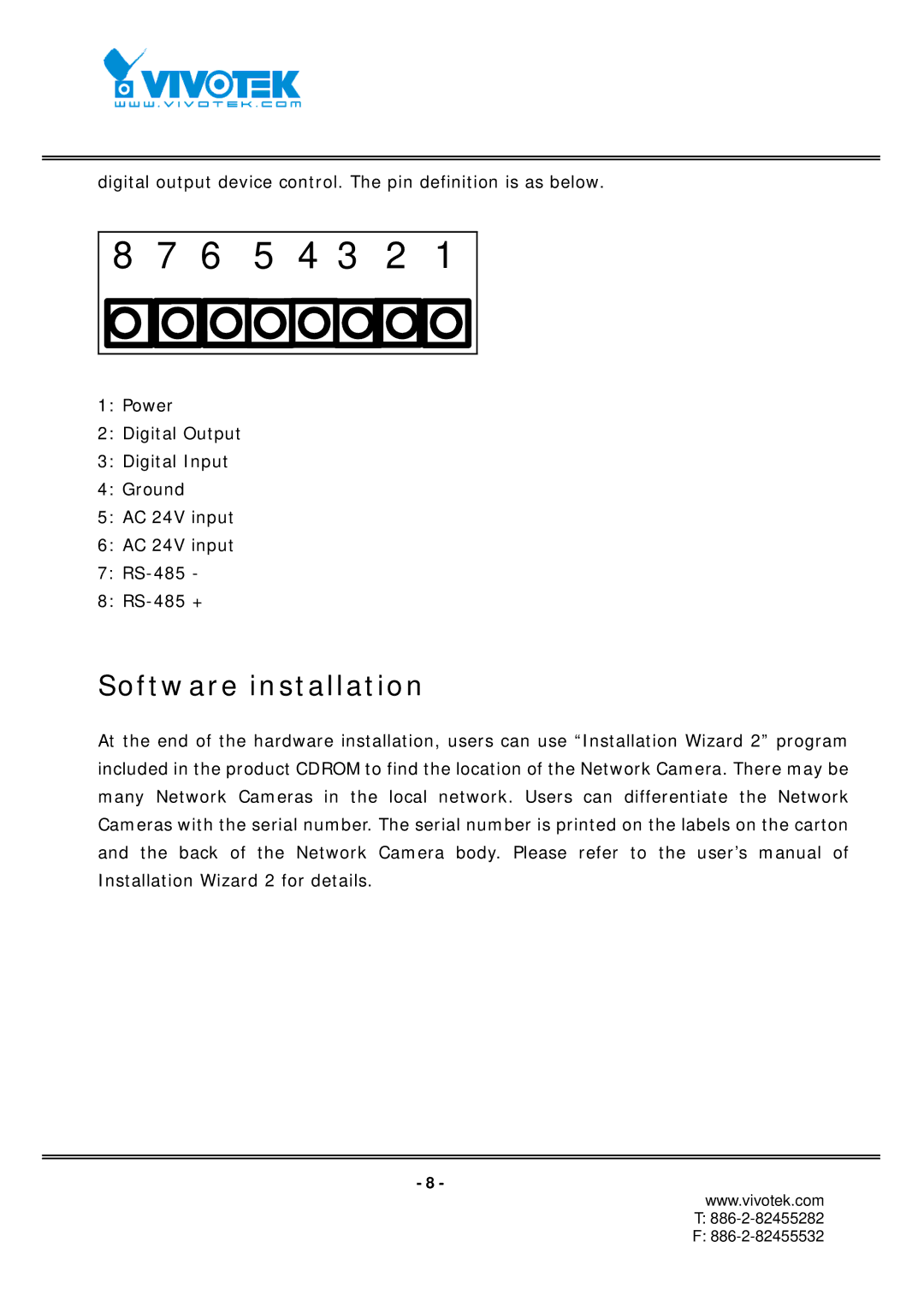
digital output device control. The pin definition is as below.
8 7 6 5 4 3 2 1
1:Power
2:Digital Output
3:Digital Input
4:Ground
5:AC 24V input
6:AC 24V input
7:
8:
Software installation
At the end of the hardware installation, users can use “Installation Wizard 2” program included in the product CDROM to find the location of the Network Camera. There may be many Network Cameras in the local network. Users can differentiate the Network Cameras with the serial number. The serial number is printed on the labels on the carton and the back of the Network Camera body. Please refer to the user’s manual of Installation Wizard 2 for details.
- 8 -
www.vivotek.com
T:
F: