PZ8111 specifications
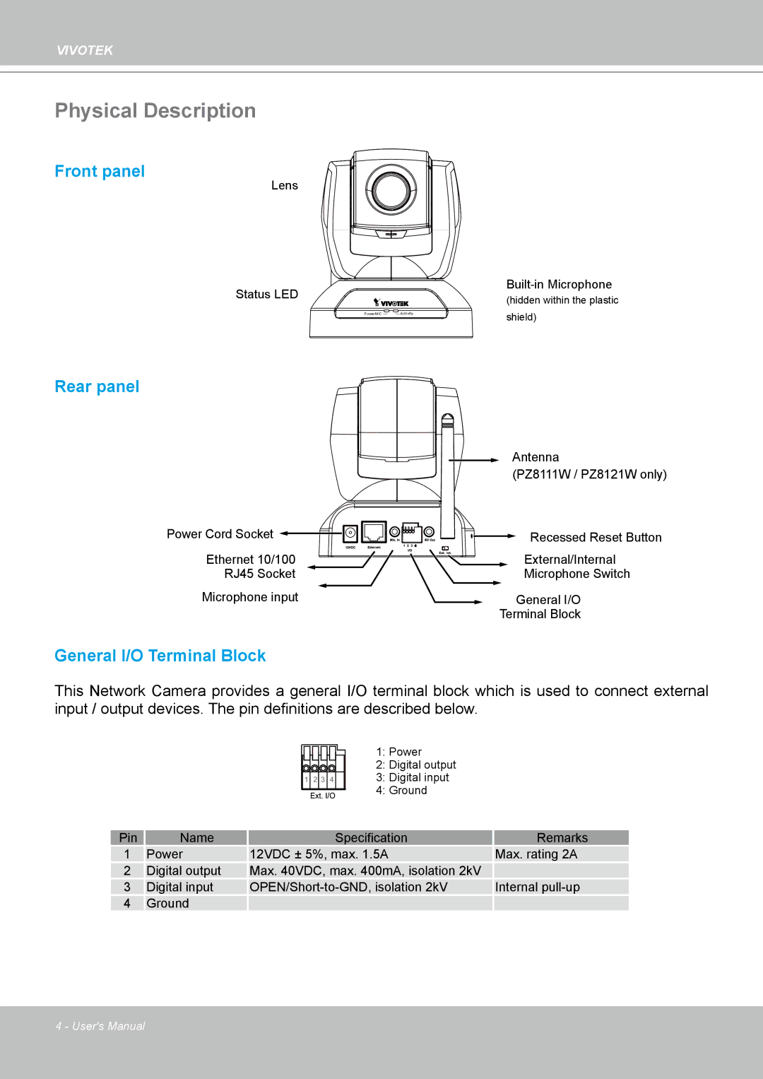
The Vivotek PZ8111 is a notable entry in the realm of advanced surveillance technology, designed to meet the demands of both commercial and residential security. This camera stands out for its impressive combination of features, technologies, and characteristics, making it an ideal solution for users seeking high-quality video monitoring.One of the key features of the PZ8111 is its ability to provide high-definition video resolution. With a capability of up to 2MP, it delivers crisp, clear images that enhance both visibility and detail, which is crucial for identifying subjects in various security situations. This ultra-clear resolution is particularly beneficial for environments that require precise surveillance, such as banks, retail stores, and public spaces.
In terms of versatility, the PZ8111 comes equipped with pan and tilt functionalities. This allows for a broader coverage area, meaning fewer cameras are needed to monitor large spaces effectively. The pan range extends up to 355 degrees, while the tilt range covers 90 degrees, enabling users to adjust the camera’s view dynamically. These features ensure that no area is left uncovered, significantly enhancing the overall efficiency of the surveillance system.
The PZ8111 also incorporates advanced day/night capabilities, including infrared illumination. This technology ensures that the camera can capture high-quality footage even in low-light conditions, providing 24/7 security monitoring. The automatic switch between color and black-and-white modes is seamless, allowing for continuous observation without compromising image clarity.
Another significant aspect of the Vivotek PZ8111 is its integration with modern network infrastructure. The camera supports Power over Ethernet (PoE), which simplifies installation by allowing both power and data to be transmitted through a single cable. This feature not only reduces installation costs but also enhances system reliability.
Furthermore, the PZ8111 is equipped with intelligent video analytics features. These tools include motion detection, tampering detection, and even people counting functions. Such capabilities empower users to set specific alerts for unusual activities, ensuring prompt responses in critical situations.
Additionally, the PZ8111 supports various streaming protocols, including RTSP and ONVIF, making it a flexible choice for integration with existing security systems. This compatibility allows for easier management and integration of security hardware, ensuring users get the most out of their investment.
Overall, the Vivotek PZ8111 is a comprehensive surveillance solution that combines high-resolution imaging, versatile pan-and-tilt functionality, advanced night vision, and intelligent analytics. Its innovative features make it an exceptional choice for businesses and homeowners alike, providing peace of mind through reliable and effective security monitoring.

