Front and rear panel descriptions
Front panel
ON
OFF
1 | 2 | 4 |
| 3 |
|
|
| VOLUME |
|
| A |
| B |
UHF DUAL CHANNEL WIRELESS | CH. A POWER CH. B |
|
|
MICROPHONE SYSTEM | MIN | MAX MIN | MAX |
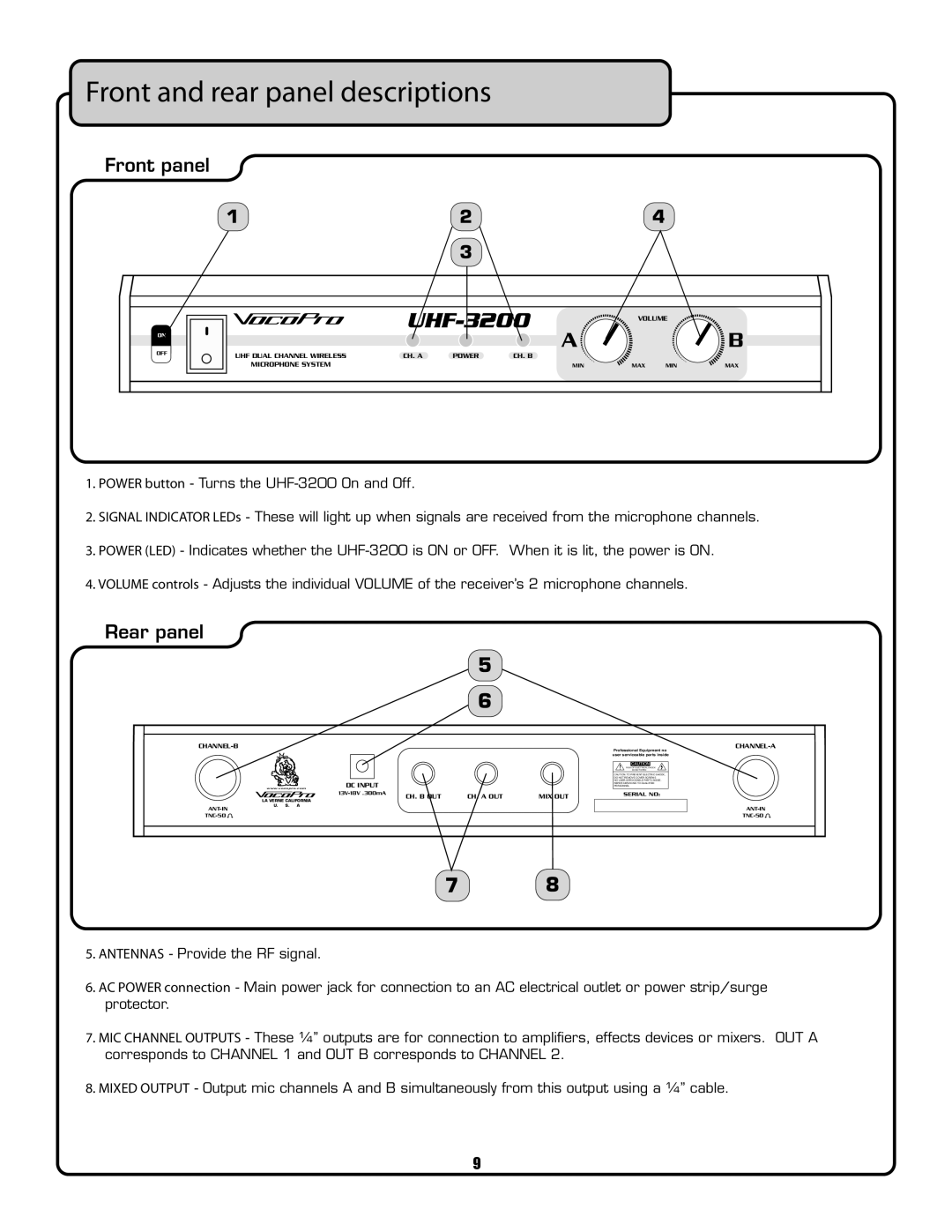
1.POWER button - Turns the
2.SIGNAL INDICATOR LEDs - These will light up when signals are received from the microphone channels.
3.POWER (LED) - Indicates whether the
4.VOLUME controls - Adjusts the individual VOLUME of the receiver’s 2 microphone channels.
Rear panel
|
| 5 |
|
|
| 6 |
|
|
|
|
|
|
| Professional Equipment no | |
|
| user serviceable parts inside | |
|
| ! | CAUTION |
|
| RISK OF ELECTRICAL SHOCK | |
|
| DO NOT OPEN | |
|
| CAUTION: TO PREVENT ELECTRIC SHOCK, | |
|
| DO NOT REMOVE COVER SCREWS | |
| DC INPUT | NO | |
| REFER SERVICING TO QUALIFIED | ||
www.vocopro.com | PERSONNEL | ||
|
| ||
|
| CH. B OUT | CH. A OUT | MIX OUT | SERIAL NO: | |
| LA VERNE CALIFORNIA |
|
| |||
U. S. A |
|
|
|
|
| |
|
|
|
|
|
| |
|
|
|
|
|
|
![]()
![]()
7 8
5.ANTENNAS - Provide the RF signal.
6.AC POWER connection - Main power jack for connection to an AC electrical outlet or power strip/surge protector.
7.MIC CHANNEL OUTPUTS - These ¼” outputs are for connection to amplifiers, effects devices or mixers. OUT A corresponds to CHANNEL 1 and OUT B corresponds to CHANNEL 2.
8.MIXED OUTPUT - Output mic channels A and B simultaneously from this output using a ¼” cable.
9