SERVICE PROCEDURES AND ADJUSTMENTS
WARNING: CERTAIN PROCEDURES IN THIS SECTION REQUIRE ELECTRICAL TEST OR MEASUREMENTS WHILE POWER IS APPLIED TO THE MACHINE. EXERCISE EXTREME CAUTION AT ALL TIMES. IF TEST POINTS ARE NOT EASILY ACCESSIBLE, DISCONNECT POWER AND FOLLOW LOCKOUT / TAGOUT PROCEDURES, ATTACH TEST EQUIPMENT AND REAPPLY POWER TO TEST.
THERMOSTAT CALIBRATION
1.Set the thermocouple in the center of the burner section to be calibrated.
2.Set the ON/OFF switch to the ON position. Adjust the thermostat knob of the burner to be calibrated to 350 degrees.
3.Allow the burners to cycle on and off at least twice. Observe the griddle heat light and thermocouple readings. The thermocouple reading should be 350 degrees plus or minus 15 degrees the instant the heating light comes on.
If the unit is not within these calibration specifications follow the steps below.
4.Gently, remove the thermostat knob from the unit without rotating the thermostat shaft.
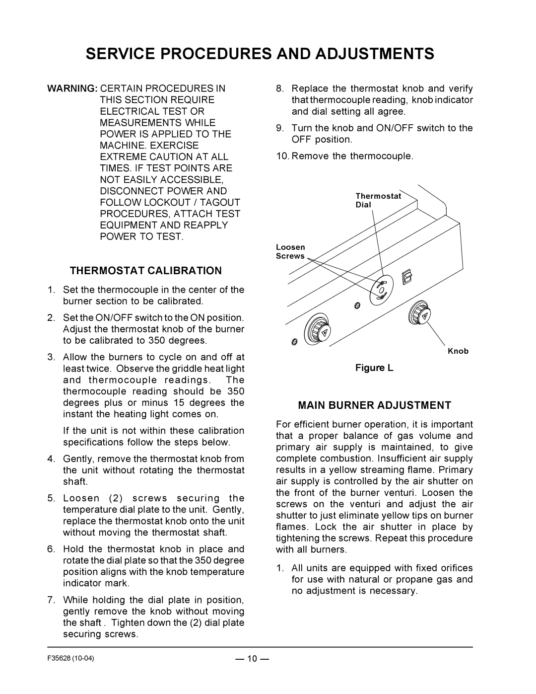
5.Loosen (2) screws securing the temperature dial plate to the unit. Gently, replace the thermostat knob onto the unit without moving the thermostat shaft.
6.Hold the thermostat knob in place and rotate the dial plate so that the 350 degree position aligns with the knob temperature indicator mark.
7.While holding the dial plate in position, gently remove the knob without moving the shaft . Tighten down the (2) dial plate securing screws.
8.Replace the thermostat knob and verify that thermocouple reading, knob indicator and dial setting all agree.
9.Turn the knob and ON/OFF switch to the OFF position.
10.Remove the thermocouple.
Thermostat
Dial
Loosen
Screws
Knob
Figure L
MAIN BURNER ADJUSTMENT
For efficient burner operation, it is important that a proper balance of gas volume and primary air supply is maintained, to give complete combustion. Insufficient air supply results in a yellow streaming flame. Primary air supply is controlled by the air shutter on the front of the burner venturi. Loosen the screws on the venturi and adjust the air shutter to just eliminate yellow tips on burner flames. Lock the air shutter in place by tightening the screws. Repeat this procedure with all burners.
1.All units are equipped with fixed orifices for use with natural or propane gas and no adjustment is necessary.
F35628 | — 10 — |