CONTROL PANEL
WARNING: DISCONNECT THE ELECTRICAL POWER TO THE MACHINE AND FOLLOW LOCKOUT / TAGOUT PROCEDURES.
1.Remove the two screws securing the control panel. One screw is located at each end of the control panel.
2.Pull the control panel forward and disconnect the electrical connector near the right end.
Panel
Connector
Remove | Control |
Screw | Panel |
Figure B
3. Reverse the procedure to install.
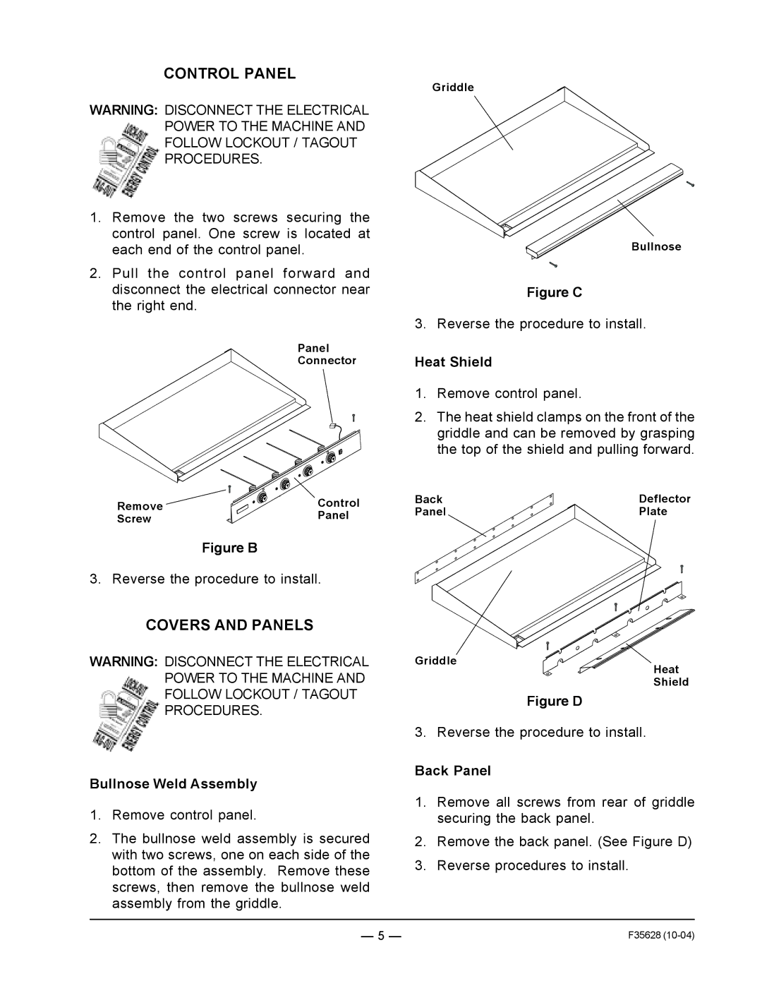
Griddle
Bullnose
Figure C
3. Reverse the procedure to install.
Heat Shield
1.Remove control panel.
2.The heat shield clamps on the front of the griddle and can be removed by grasping the top of the shield and pulling forward.
Back | Deflector |
Panel | Plate |
COVERS AND PANELS
WARNING: DISCONNECT THE ELECTRICAL POWER TO THE MACHINE AND FOLLOW LOCKOUT / TAGOUT PROCEDURES.
Bullnose Weld Assembly
1.Remove control panel.
2.The bullnose weld assembly is secured with two screws, one on each side of the bottom of the assembly. Remove these screws, then remove the bullnose weld assembly from the griddle.
Griddle
Heat
Shield
Figure D
3. Reverse the procedure to install.
Back Panel
1.Remove all screws from rear of griddle securing the back panel.
2.Remove the back panel. (See Figure D)
3.Reverse procedures to install.
— 5 — | F35628 |