PROTOCOL GUIDELINES
While many RF solutions impose data formatting and balancing requirements, Linx RF modules do not encode or packetize the signal content in any manner. The received signal will be affected by such factors as noise, edge jitter, and interference, but it is not purposefully manipulated or altered by the modules. This gives the designer tremendous flexibility for protocol design and interface.
Despite this transparency and ease of use, it must be recognized that there are distinct differences between a wired and a wireless environment. Issues such as interference and contention must be understood and allowed for in the design process. To learn more about protocol considerations, we suggest you read Linx Application Note
Errors from interference or changing signal conditions can cause corruption of the data packet, so it is generally wise to structure the data being sent into small packets. This allows errors to be managed without affecting large amounts of data. A simple checksum or CRC could be used for basic error detection. Once an error is detected, the protocol designer may wish to simply discard the corrupt data or implement a more sophisticated scheme to correct it.
INTERFERENCE CONSIDERATIONS
The RF spectrum is crowded and the potential for conflict with other unwanted sources of RF is very real. While all RF products are at risk from interference, its effects can be minimized by better understanding its characteristics.
Interference may come from internal or external sources. The first step is to eliminate interference from noise sources on the board. This means paying careful attention to layout, grounding, filtering, and bypassing in order to eliminate all radiated and conducted interference paths. For many products, this is straightforward; however, products containing components such as switching power supplies, motors, crystals, and other potential sources of noise must be approached with care. Comparing your own design with a Linx evaluation board can help to determine if and at what level
External interference can manifest itself in a variety of ways.
Although technically it is not interference, multipath is also a factor to be understood. Multipath is a term used to refer to the signal cancellation effects that occur when RF waves arrive at the receiver in different phase relationships. This effect is a particularly significant factor in interior environments where objects provide many different signal reflection paths. Multipath cancellation results in lowered signal levels at the receiver and, thus, shorter useful distances for the link.
TYPICAL APPLICATIONS
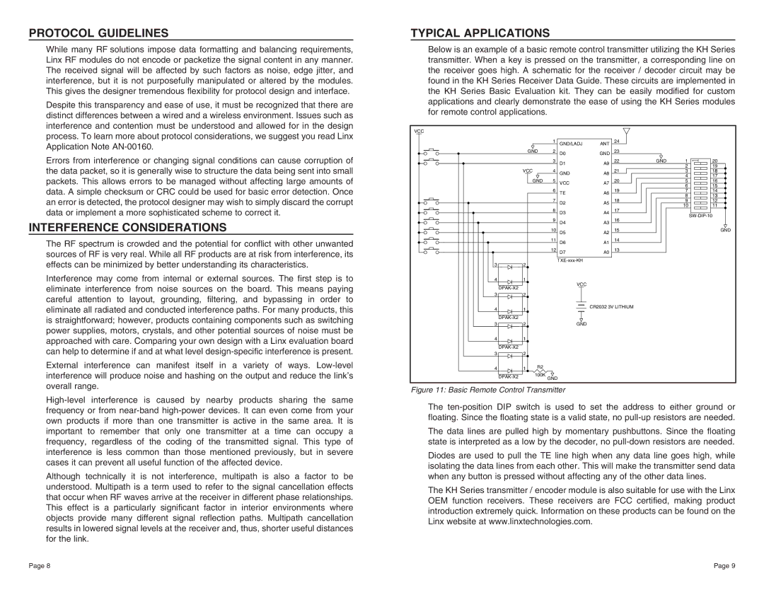
Below is an example of a basic remote control transmitter utilizing the KH Series transmitter. When a key is pressed on the transmitter, a corresponding line on the receiver goes high. A schematic for the receiver / decoder circuit may be found in the KH Series Receiver Data Guide. These circuits are implemented in the KH Series Basic Evaluation kit. They can be easily modified for custom applications and clearly demonstrate the ease of using the KH Series modules for remote control applications.
VCC |
|
|
|
|
|
|
|
| |
|
|
| 1 | GND/LADJ | ANT | 24 |
|
|
|
|
|
|
|
|
|
|
| ||
|
| GND | 2 | D0 | GND | 23 |
|
|
|
|
|
| 3 | D1 | A9 | 22 | GND | 1 | 20 |
|
| VCC |
|
|
|
|
| 2 | 19 |
|
| 4 | GND | A8 | 21 |
| 3 | 17 | |
|
|
|
|
|
|
|
| 4 | |
|
| GND | 5 | VCC | A7 | 20 |
| 5 | 16 |
|
|
|
|
|
| 19 |
| 6 |
|
|
|
| 6 | TE | A6 |
| 7 | 14 | |
|
|
| 7 |
|
| 18 |
| 8 |
|
|
|
| D2 | A5 |
| 9 | 12 | ||
|
|
| 8 |
|
| 17 |
| 10 | 11 |
|
|
| D3 | A4 |
|
| |||
|
|
| 9 |
|
| 16 |
|
| |
|
|
| D4 | A3 |
|
|
| ||
|
|
| 10 | D5 | A2 | 15 |
|
| GND |
|
|
| 11 | D6 | A1 | 14 |
|
|
|
|
|
| 12 | D7 | A0 | 13 |
|
|
|
|
|
|
|
|
|
|
| ||
3 | 2 |
|
|
|
|
|
| ||
|
|
|
|
|
|
| |||
4 | 1 |
|
|
|
|
|
|
| |
| VCC | |
|
| |
3 | 2 |
|
4 | 1 | CR2032 3V LITHIUM |
| ||
|
| |
3 | 2 | GND |
41
32
41 R2
100K | ||
GND | ||
|
Figure 11: Basic Remote Control Transmitter
The
The data lines are pulled high by momentary pushbuttons. Since the floating state is interpreted as a low by the decoder, no
Diodes are used to pull the TE line high when any data line goes high, while isolating the data lines from each other. This will make the transmitter send data when any button is pressed without affecting any of the other data lines.
The KH Series transmitter / encoder module is also suitable for use with the Linx OEM function receivers. These receivers are FCC certified, making product introduction extremely quick. Information on these products can be found on the Linx website at www.linxtechnologies.com.
Page 8 | Page 9 |