PIN ASSIGNMENTS
1 | LADJ/GND ANT | 24 | |
2 | D0 | GND | 23 |
3 | D1 | A9 | 22 |
4 | GND | A8 | 21 |
5 | VCC | A7 | 20 |
6 | TE | A6 | 19 |
7 | D2 | A5 | 18 |
8 | D3 | A4 | 17 |
9 | D4 | A3 | 16 |
10 | D5 | A2 | 15 |
11 | D6 | A1 | 14 |
12 | D7 | A0 | 13 |
Figure 6: KH Series Transmitter Pinout (Top View)
PIN DESCRIPTIONS
Pin # | Name | Description | |
|
| Level Adjust. This line can be used to adjust the output | |
1 | GND / LADJ | power level of the transmitter. Connecting to GND will give | |
|
| the highest output, while placing a resistor to GND will | |
|
| lower the output level. | |
|
|
| |
|
| Data Input Lines. When TE goes high, the module will | |
2, 3, | D0 - D1 | encode the state of these lines for transmission. Upon | |
receipt of a valid transmission, the receiver / decoder will | |||
| |||
|
| replicate these lines on its output lines. | |
|
|
| |
4 | GND | Analog Ground | |
|
|
| |
5 | VCC | Supply Voltage | |
|
| Transmit Enable Line. When this line goes high, the | |
6 | TE | module will encode the states of the address and data lines | |
|
| into a packet and transmit the packet three times. | |
|
|
| |
|
| Address Lines. The state of these lines must match the | |
| state of the receiver’s address lines in order for a | ||
|
| transmission to be accepted. | |
|
|
| |
23 | GND | Analog Ground | |
|
|
| |
24 | ANT | ||
|
|
|
MODULE DESCRIPTION
The KH Series transmitter / encoder module combines a
|
|
| Address Inputs |
| |
|
| TX Enable |
|
| |
| SAW |
|
|
| |
|
|
|
|
| |
50Ω RF OUT | Oscillator |
| Divider |
| Parallel |
|
|
| |||
|
| OSC | Inputs | ||
(ANT) |
| Sync |
| ||
|
|
| |||
|
|
|
| ||
Keyed Output |
| Counter | GATE |
| |
|
|
| |||
|
|
|
| ||
| RF Amplifier | Buffer |
| ||
Output Isolation |
|
| |||
|
|
|
|
| |
& Filter |
|
|
|
|
|
RF STAGE | ENCODER STAGE |
| |||
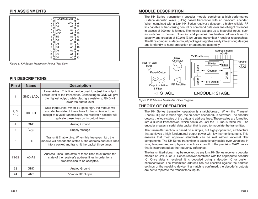
Figure 7: KH Series Transmitter Block Diagram
THEORY OF OPERATION
The KH Series transmitter operation is straightforward. When the Transmit Enable (TE) line is taken high, the
The transmitter section is based on a simple, but
The transmitted signal may be received by any Linx KH Series receiver / decoder module or Linx LC or LR Series receiver combined with the appropriate decoder IC. Once data is received, it is decoded using a decoder IC or custom microcontroller. The transmitted address bits are checked against the address settings of the receiving device. If a match is confirmed, the decoder’s outputs are set to replicate the transmitter’s inputs.
Page 4 | Page 5 |