COMPONENTS AND DESCRIPTION
COMPONENTS | sprayer model (refer to Spray |
Gun/Tip Chart, below). |
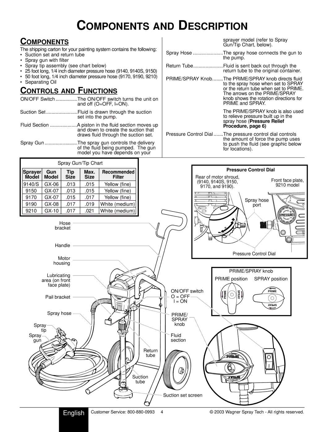
The shipping carton for your painting system contains the following:
• Suction set and return tube | Spray Hose | The spray hose connects the gun to | ||
| the pump. | |||
• Spray gun with filter |
|
|
| |
|
|
|
| |
• Spray tip assembly (see chart below) | Return Tube | Fluid is sent back out through the | ||
• 25 foot long, 1/4 inch diameter pressure hose (9140, 9140S, 9150) |
| return tube to the original container. | ||
• 50 foot long, 1/4 inch diameter pressure hose (9170, 9190, 9210) | PRIME/SPRAY Knob | The PRIME/SPRAY knob directs fluid | ||
• Separating Oil |
|
| ||
|
|
| to the spray hose when set to SPRAY | |
CONTROLS AND FUNCTIONS |
|
| or the return tube when set to PRIME. | |
|
| The arrows on the PRIME/SPRAY | ||
|
| |||
ON/OFF Switch | The ON/OFF switch turns the unit on |
| knob shows the rotation directions for | |
| and off (O=OFF, l=ON). |
| PRIME and SPRAY. | |
Suction Set | Fluid is drawn through the suction |
| The PRIME/SPRAY knob is also used | |
| set into the pump. |
| to relieve pressure built up in the | |
Fluid Section | A piston in the fluid section moves up |
| spray hose (Pressure Relief | |
| Procedure, page 6) | |||
| and down to create the suction that | Pressure Control Dial | The pressure control dial controls | |
| draws fluid through the suction set. | |||
Spray Gun | The spray gun controls the delivery |
| the amount of force the pump uses | |
| to push the fluid (see graphic below | |||
| of the fluid being pumped. The gun |
| for locations). | |
| model you have depends on your |
|
| |
| Spray Gun/Tip Chart |
|
|
| ||||
Sprayer | Gun | Tip | Max. | Recommended | Pressure Control Dial |
| ||
|
|
| ||||||
Model | Model | Size | Size | Filter | Rear of motor shroud, | Front face plate, | ||
9140/S | .013 | .015 | Yellow (fine) | (9140, 9140S, 9150, | ||||
| 9210 model | |||||||
9170, and 9190). |
| |||||||
9150 | .013 | .015 | Yellow (fine) |
|
| |||
|
|
| ||||||
9170 | .015 | .017 | Yellow (fine) |
| Spray hose |
| ||
9190 | .017 | .019 | White (medium) |
|
| |||
| port |
| ||||||
9210 | .017 | .021 | White (medium) |
|
|
| ||
|
| Hose |
|
|
|
|
| |
| bracket |
|
|
|
|
| ||
| Handle |
|
|
|
|
| ||
| Motor |
|
| Pressure Control Dial |
| |||
|
|
|
|
|
| |||
| housing |
|
|
|
|
| ||
Lubricating area (on front face plate)
Pail bracket
Spray hose
Spray
tip
Spray
gun ![]()
![]()
ON/OFF switch
O = OFF
l = ON
 PRIME/ SPRAY
knob
Fluid section
Return
tube
Suction
tube
PRIME/SPRAY knob
PRIME position SPRAY position
PRIME | SPRAY | PRIME |
|
| |
|
| SPRAY |
O
![]() Suction set screen
Suction set screen
| English | Customer Service: | © 2003 Wagner Spray Tech - All rights reserved. |
|
|
|
|
