Wiring
Power must be shut off at the circuit breaker before performing any wiring. Be sure to follow Local and NEC electrical codes. To provide safe operation, the Aqua Rite® must be properly grounded and bonded.
Input Power For stand alone operation:
Wire the Aqua Rite to the LOAD SIDE of the filter pump timer. It is very important that the Aqua Rite is powered only when the pump is running.
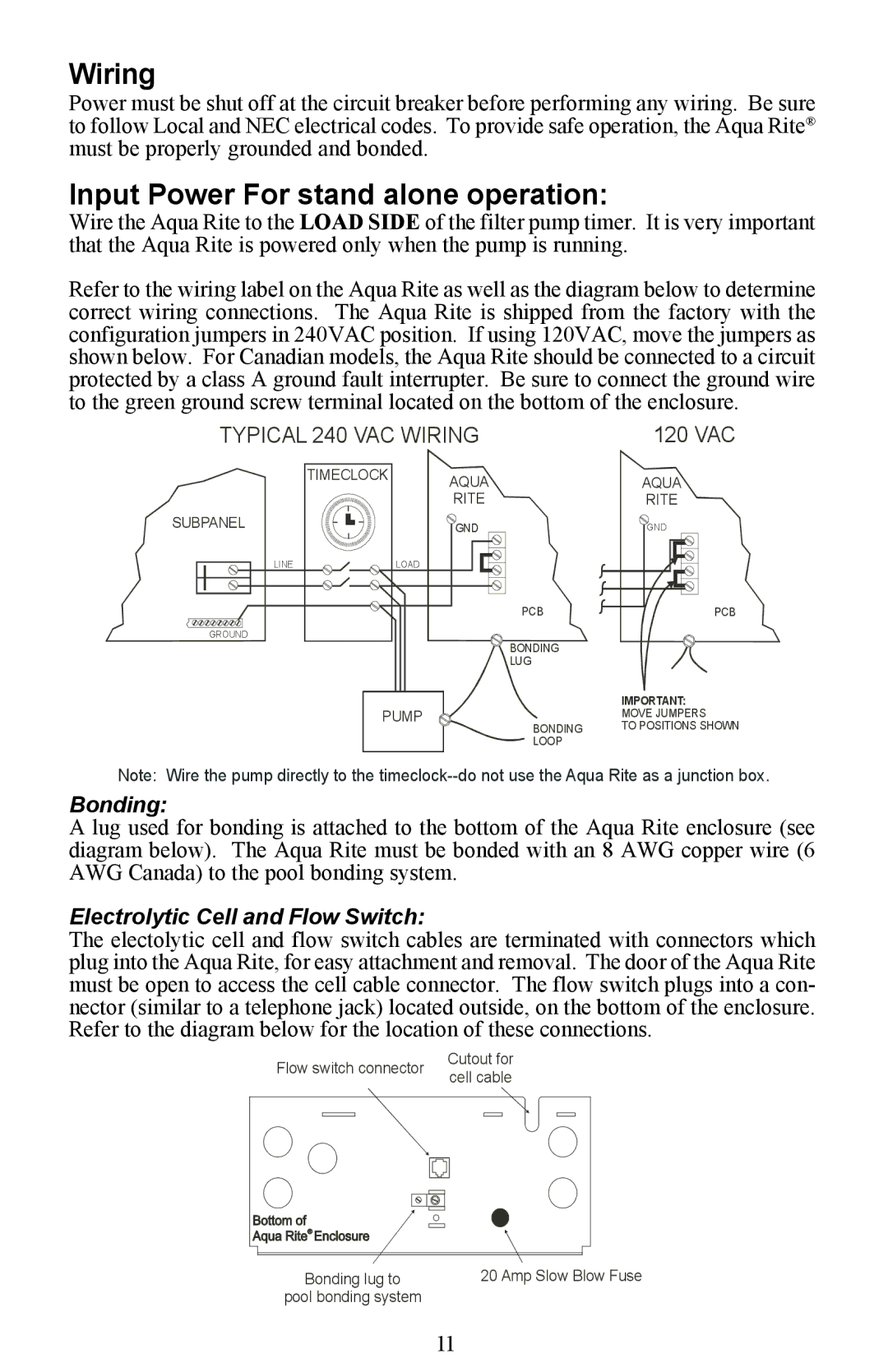
Refer to the wiring label on the Aqua Rite as well as the diagram below to determine correct wiring connections. The Aqua Rite is shipped from the factory with the configuration jumpers in 240VAC position. If using 120VAC, move the jumpers as shown below. For Canadian models, the Aqua Rite should be connected to a circuit protected by a class A ground fault interrupter. Be sure to connect the ground wire to the green ground screw terminal located on the bottom of the enclosure.
TYPICAL 240 VAC WIRING | 120 VAC | ||
| TIMECLOCK | AQUA | AQUA |
|
| ||
|
| RITE | RITE |
SUBPANEL |
| GND | GND |
LINE | LOAD |
|
|
|
| PCB | PCB |
GROUND |
| BONDING |
|
|
|
| |
|
| LUG |
|
| PUMP |
| IMPORTANT: |
|
| MOVE JUMPERS | |
|
| BONDING | TO POSITIONS SHOWN |
LOOP
Note: Wire the pump directly to the
Bonding:
A lug used for bonding is attached to the bottom of the Aqua Rite enclosure (see diagram below). The Aqua Rite must be bonded with an 8 AWG copper wire (6 AWG Canada) to the pool bonding system.
Electrolytic Cell and Flow Switch:
The electolytic cell and flow switch cables are terminated with connectors which plug into the Aqua Rite, for easy attachment and removal. The door of the Aqua Rite must be open to access the cell cable connector. The flow switch plugs into a con- nector (similar to a telephone jack) located outside, on the bottom of the enclosure. Refer to the diagram below for the location of these connections.
Flow switch connector | Cutout for | |
cell cable | ||
|
Bonding lug to | 20 Amp Slow Blow Fuse |
pool bonding system |
|
11