ESP45


PS/BC Installation


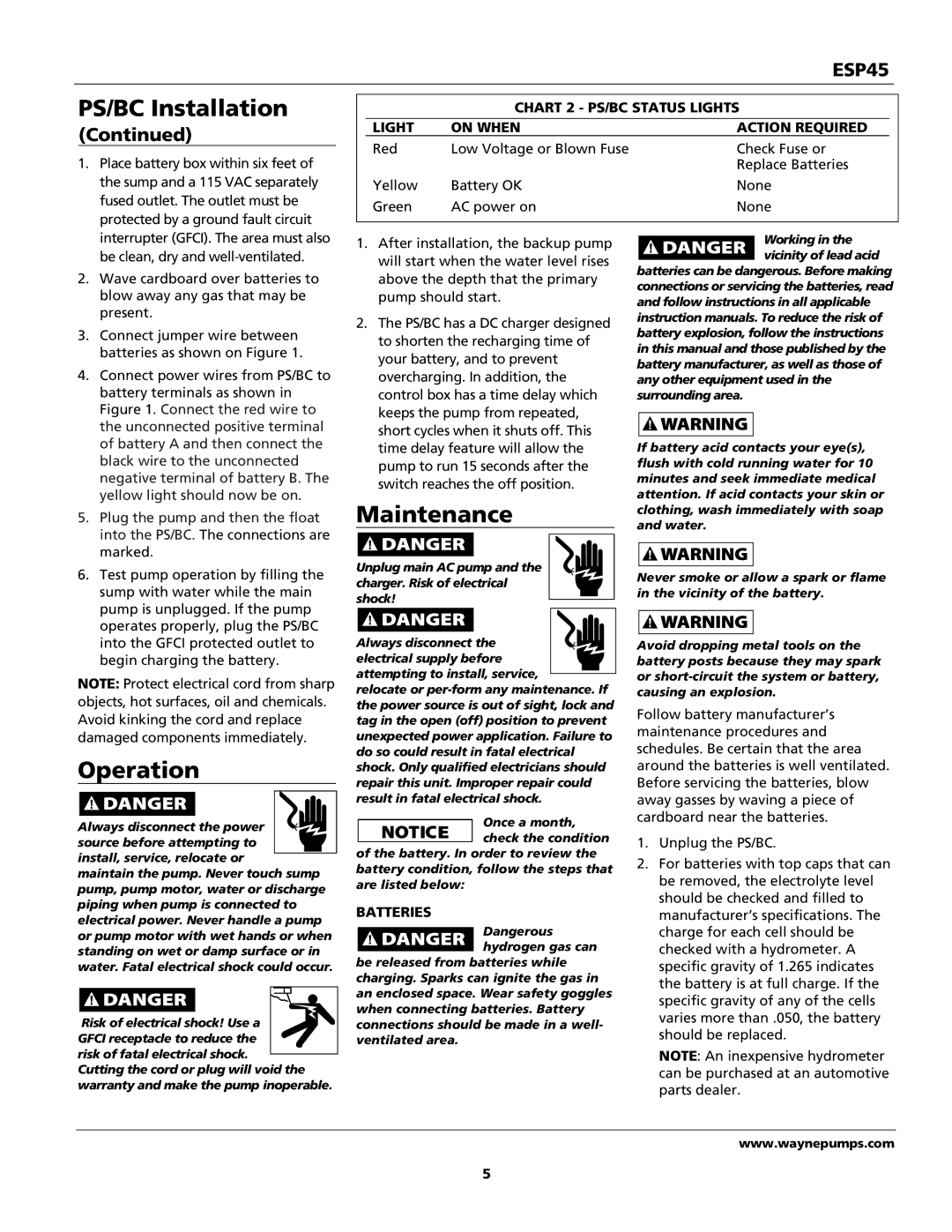
CHART 2 - PS/BC STATUS LIGHTS


(Continued)


LIGHT

ON WHEN


ACTION REQUIRED


Red

Low Voltage or Blown Fuse


Check Fuse or


1. Place battery box within six feet of


Replace Batteries


the sump and a 115 VAC separately


Yellow

Battery OK


None


fused outlet. The outlet must be


Green

AC power on


None


protected by a ground fault circuit


interrupter (GFCI). The area must also


1. After installation, the backup pump


Working in the


be clean, dry and well-ventilated.


vicinity of lead acid


will start when the water level rises


batteries can be dangerous. Before making


2.

Wave cardboard over batteries to


above the depth that the primary


connections or servicing the batteries, read


blow away any gas that may be


pump should start.


and follow instructions in all applicable


present.


2. The PS/BC has a DC charger designed

instruction manuals. To reduce the risk of


3.

Connect jumper wire between


battery explosion, follow the instructions


to shorten the recharging time of


batteries as shown on Figure 1.


in this manual and those published by the


your battery, and to prevent


4. Connect power wires from PS/BC to


battery manufacturer, as well as those of


overcharging. In addition, the


any other equipment used in the


battery terminals as shown in


control box has a time delay which

surrounding area.


Figure 1. Connect the red wire to


keeps the pump from repeated,


the unconnected positive terminal


short cycles when it shuts off. This


of battery A and then connect the


time delay feature will allow the

If battery acid contacts your eye(s),


black wire to the unconnected


pump to run 15 seconds after the

flush with cold running water for 10


negative terminal of battery B. The


switch reaches the off position.

minutes and seek immediate medical


yellow light should now be on.


attention. If acid contacts your skin or


Maintenance


5.

Plug the pump and then the float


clothing, wash immediately with soap


and water.


into the PS/BC. The connections are


marked.


Unplug main AC pump and the


6.

Test pump operation by filling the


Never smoke or allow a spark or flame


charger. Risk of electrical


sump with water while the main


in the vicinity of the battery.


shock!


pump is unplugged. If the pump


operates properly, plug the PS/BC


into the GFCI protected outlet to


Always disconnect the


Avoid dropping metal tools on the


begin charging the battery.


electrical supply before


battery posts because they may spark


NOTE: Protect electrical cord from sharp


attempting to install, service,


or short-circuit the system or battery,


relocate or per-form any maintenance. If

causing an explosion.


objects, hot surfaces, oil and chemicals.


the power source is out of sight, lock and

Follow battery manufacturer’s


Avoid kinking the cord and replace


tag in the open (off) position to prevent


maintenance procedures and


damaged components immediately.


unexpected power application. Failure to


schedules. Be certain that the area


Operation


do so could result in fatal electrical


shock. Only qualified electricians should

around the batteries is well ventilated.


repair this unit. Improper repair could

Before servicing the batteries, blow


result in fatal electrical shock.

away gasses by waving a piece of


Once a month,

cardboard near the batteries.


Always disconnect the power


source before attempting to


check the condition

1. Unplug the PS/BC.


of the battery. In order to review the


install, service, relocate or


2. For batteries with top caps that can


battery condition, follow the steps that


maintain the pump. Never touch sump


be removed, the electrolyte level


are listed below:


pump, pump motor, water or discharge


should be checked and filled to


piping when pump is connected to


BATTERIES


manufacturer’s specifications. The


electrical power. Never handle a pump


Dangerous

charge for each cell should be


or pump motor with wet hands or when


standing on wet or damp surface or in


hydrogen gas can

checked with a hydrometer. A


water. Fatal electrical shock could occur.


be released from batteries while

specific gravity of 1.265 indicates


charging. Sparks can ignite the gas in

the battery is at full charge. If the


an enclosed space. Wear safety goggles

specific gravity of any of the cells


when connecting batteries. Battery


Risk of electrical shock! Use a


varies more than .050, the battery


connections should be made in a well-


should be replaced.


GFCI receptacle to reduce the


ventilated area.


risk of fatal electrical shock.


NOTE: An inexpensive hydrometer


Cutting the cord or plug will void the


can be purchased at an automotive


warranty and make the pump inoperable.


parts dealer.


www.waynepumps.com

5

Page 5
Image 5
Wayne 353601-001 specifications Maintenance, Operation, Chart 2 PS/BC Status Lights On When Action Required, Batteries

353601-001 specifications

The Wayne 353601-001 is a state-of-the-art fuel dispenser that reflects a perfect blend of modern technology and user-friendly design, positioned to meet the evolving needs of the fuel retail industry. This dispenser is engineered for efficiency, reliability, and exceptional performance, making it an ideal choice for gas stations and convenience stores.

One of the standout features of the Wayne 353601-001 is its robust construction, designed to withstand the rigors of daily use in bustling service stations. The dispenser is equipped with weather-resistant components, ensuring durability and longevity in various environmental conditions. Its sleek design allows for easy maintenance, further enhancing its practicality for operators.

In terms of technology, the Wayne 353601-001 employs advanced electronic systems that facilitate precise fuel measurement and fast transaction processing. The unit incorporates advanced flow meter technology, which ensures accurate dispensing with minimal product loss. This precision not only fosters consumer trust but also enhances operational efficiency, ultimately impacting the profitability of the business.

The dispenser's interface is intuitive and user-friendly, featuring high-resolution displays that provide clear information to customers. The keypad is designed for easy navigation, and the touchscreen option allows for interactive features, including loyalty programs and promotional offers. This level of engagement can significantly enhance the customer experience, encouraging repeat business.

The Wayne 353601-001 also includes integration capabilities for various payment systems, supporting both traditional card transactions and modern contactless payment options. This versatility ensures that customers can complete their purchases conveniently, adapting to the shifts in consumer preferences towards digital payment methods.

Safety is a paramount consideration in the design of the Wayne 353601-001. It includes multiple safety features such as emergency shut-off systems, leak detection, and automatic shut-off valves that are in line with industry standards. These features not only protect the consumer but also safeguard the environment, aligning with best practices for fuel dispensing operations.

In summary, the Wayne 353601-001 stands out in the marketplace due to its combination of durability, advanced technology, user-centric design, and safety features. Whether enhancing consumer satisfaction or streamlining operational efficiency, this fuel dispenser is a reliable solution for the evolving demands of the fueling industry.