2411, 2415 specifications
Wayne-Dalton has long been recognized as a leading manufacturer of high-quality garage doors, and among their popular models are the Wayne-Dalton 2415 and 2411. These models are designed to combine durability, aesthetic appeal, and innovative technology, making them suitable for both residential and commercial applications.The Wayne-Dalton 2415 is known for its robust construction and versatility. Constructed with superior insulation properties, this model features a three-layer construction that includes an outer steel layer, an insulation core, and an inner steel layer. This design not only enhances thermal performance, helping to maintain a consistent indoor temperature and energy efficiency, but also provides excellent soundproofing qualities. The 2415 is available in various styles and colors, allowing homeowners to customize their garage doors to fit their architectural needs.
In contrast, the Wayne-Dalton 2411 offers a more economical solution without compromising on quality. This model features a two-layer construction that still provides adequate insulation and strength, making it ideal for moderate climates. The 2411 is particularly appealing for homeowners looking for a budget-friendly option that doesn’t skimp on style. It comes with a range of finishes and decorative hardware, ensuring that it can enhance the curb appeal of any home.
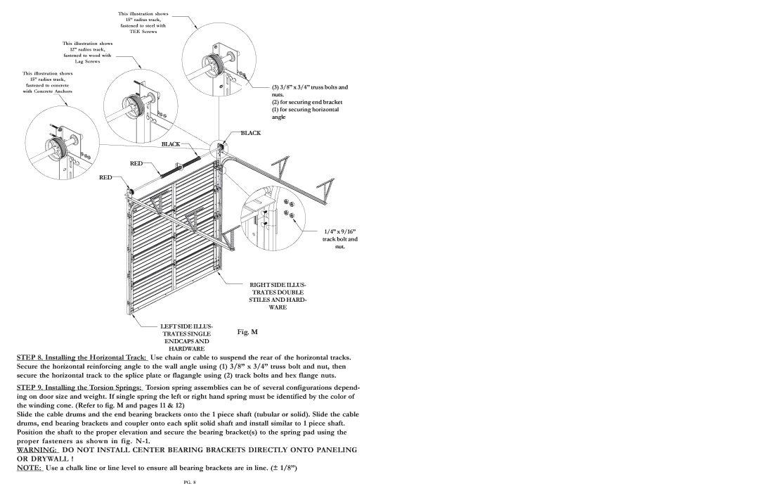
Both models are equipped with Wayne-Dalton's patented TorqueMaster® system, which features an end-mounted spring design that is enclosed in a solid steel tube. This system offers enhanced safety by eliminating exposed springs, reducing the risk of injury during operation. Additionally, both the 2415 and 2411 are compatible with Wayne-Dalton’s easy-lift panel design, making them easy to operate manually or with an automatic opener.
Safety features are also a priority in these models. They come with pinch-resistant design that minimizes the risk of injury to fingers when the door is in operation. The doors are tested for durability and wear, ensuring that they can withstand the test of time and continue to function without frequent maintenance.
In summary, the Wayne-Dalton 2415 and 2411 garage doors present homeowners with excellent options tailored to varying needs, whether it is maximum insulation, cost-effective solutions, or advanced safety features. Their combination of durability, aesthetic appeal, and cutting-edge technology makes them a standout choice in today's market.

