Door width |
+ |
Flag angle |
Nail |
Section.
Important: Failure to remove nail before attempting to raise door could cause permanent damage to top section.
Note: If an idrive® opener will be installed, position horizontal tracks slightly above level.
Top section |
to |
Flag |
angle |
Top |
section |
Vertical track |
against track rollers |
Bottom rail Quick Install Horizontal track
![]()
![]()
Flag angle upper slot
Vertical track
Stud plate
Bottom rail Fully | Flagangle | |
Adjustable | Track bolt | |
Horizontal |
|
|
track |
|
|
|
| |
Flange hex |
| Washer |
nuts |
| Top rail of |
|
| |
|
| horizontal |
Flag angle |
| track |
upper slot |
| |
Vertical |
| Flange hex |
track |
| nut |
| ||
15 | Horizontal Tracks/Q.I Flag Angles | |
Tools: Ratchet wrench, 9/16” Socket, 9/16” Wrench, level, Step ladder | ||
|
Note: If you have Quick Install flag angles, complete this step.
To install horizontal track, place the top rail end over the top track roller of the top section. Align key slot of the bottom rail end of horizontal track with the Quick Install tab of the flag angle. Push curved portion of horizontal track down to lock in place.
![]() WARNING
WARNING
Do not raise door until horizontal tracks are secured at rear, as outlined in Step, Rear Back Hangs, or door could fall from overhead position causing severe or fatal injury.
Level the horizontal track assembly and bolt the top rail of the horizontal track to the encoun- tered slot in the flag angle using (1)
Remove the nail that was temporarily holding the top section in place, installed in step, Top Section.
Important: Failure to remove nail before attempting to raise door could cause permanent damage to top section.
Note: If an idrive® opener will be installed, position horizontal tracks slightly above level.
|
| Flagangle | |
|
|
| |
|
|
| Track bolt |
Flag angle |
|
|
|
Bottom rail |
|
|
|
of horizontal | Quick Install |
|
|
track | tab in place |
| Washer |
Quick |
|
| |
|
| Top rail of | |
Install | Tracks flush |
| |
| horizontal | ||
tab |
|
| |
Key slot |
| track | |
|
| ||
|
|
| |
|
|
| Flange hex |
Vertical | Vertical |
| nut |
|
| ||
track | track |
|
|
Horizontal Tracks/F.A. Flag Angles
16 Tools: Ratchet wrench, 7/16” Socket, 9/16” Socket, 9/16” Wrench, level, Step ladder, Flat tip screwdriver
Note: If you have Fully Adjustable flag angles, complete this step.
To install horizontal track, place the top rail end over the top track roller of the top section. Align the bottom rail end of the horizontal track with the top of the vertical track. If you have Quick Install horizontal track, tighten the bottom rail of the horizontal track to the flag angle with (1) stud plate and (2)
![]() WARNING
WARNING
Do not raise door until horizontal tracks are secured at rear, as outlined in step, Rear Back Hangs, or door could fall from overhead position causing severe or fatal injury.
Level the horizontal track assembly and bolt the top rail of the horizontal track to the encoun- tered slot in the flag angle using (1)
Remove the nail that was temporarily holding the top section in place, installed in step, Top
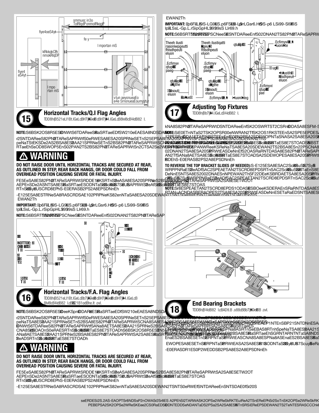
17 | Adjusting Top Fixtures | |
Tools: 7/16” Wrench, Step ladder | ||
|
With horizontal tracks installed, you can now adjust the LHR top brackets.
NOTE: Depending on your application, you may need to reverse the top bracket slide for more adjustment, if needed, prior to securing it to the top bracket base.
To adjust the top bracket slides: Loosen the (2)
To reverse the top bracket slides (if needed): Remove the two 1/4” - 20 x 5/8” carriage bolts, two retention washers and two 1/4” - 20 flanged hex nuts. Flip the top bracket slide in the opposite direction. Loosely fasten the top bracket slide to the bracket using two 1/4” - 20 x 5/8” carriage bolts, two retention washers and two 1/4” - 20 flanged hex nuts, as shown.
NOTE: The retention washers must be fully seated against the top bracket base to ensure the
| Roller |
Low headroom | (2) 1/4” - 20 |
horizontal track | Flange hex nuts |
Top bracket |
|
slide | Top section |
Top bracket |
|
assembly |
|
|
| Top bracket slide | |
(2) 1/4” - 20 |
| (2) Retention washers | |
|
| ||
Flange hex nuts |
| Slotted hole of top | |
|
| bracket base | |
Top bracket | (2) 1/4” - 20 x 5/8” | ||
Carriage bolts | |||
feature | |||
slide reversed |
|
18 | End Bearing Brackets | |
Tools: Step ladder, Power drill, 7/16” Socket driver | ||
|
NOTE: Right and left hand is always determined from inside the garage looking out.
End bearing brackets are right and left hand. Align the bottom edge of left end bearing bracket with the top edge of the flag angle. Maintaining this alignment, also align the right edge of the end bearing bracket with the right edge of the flag angle.
Secure the end bearing bracket to the jamb using (3) 5/16” x
10
Please Do Not Return This Product To The Store. Contact your local
refer to your local yellow pages business listings or go to the Find a Dealer section online at