11 | Top Fixtures | |
Tools: Power drill, 7/16” Socket driver, Phillips screwdriver | ||
|
NOTE: The top low headroom brackets come
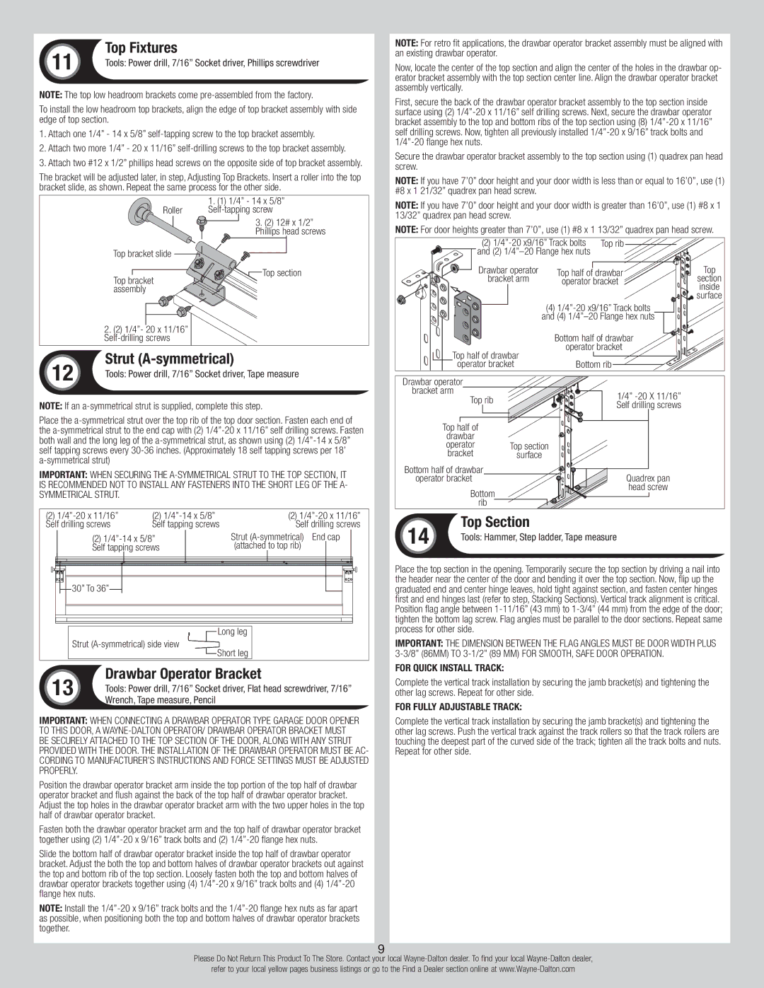
To install the low headroom top brackets, align the edge of top bracket assembly with side edge of top section.
1.Attach one 1/4” - 14 x 5/8”
2.Attach two more 1/4” - 20 x 11/16”
3.Attach two #12 x 1/2” phillips head screws on the opposite side of top bracket assembly.
The bracket will be adjusted later, in step, Adjusting Top Brackets. Insert a roller into the top bracket slide, as shown. Repeat the same process for the other side.
| 1. (1) 1/4” - 14 x 5/8” |
Roller | |
| 3. (2) 12# x 1/2” |
| Phillips head screws |
Top bracket slide |
|
Top bracket | Top section |
| |
assembly |
|
2. (2) 1/4”- 20 x 11/16” |
|
|
12 | Strut | |
Tools: Power drill, 7/16” Socket driver, Tape measure | ||
|
NOTE: If an
Place the
IMPORTANT: When securing the
(2) | (2) |
| (2) | |||
Self drilling screws | Self tapping screws |
| Self drilling screws | |||
| (2) |
| Strut |
| ||
| Self tapping screws |
| (attached | to top rib) |
| |
|
|
|
|
|
|
|
|
|
|
|
|
|
|
NOTE: For retro fit applications, the drawbar operator bracket assembly must be aligned with an existing drawbar operator.
Now, locate the center of the top section and align the center of the holes in the drawbar op- erator bracket assembly with the top section center line. Align the drawbar operator bracket assembly vertically.
First, secure the back of the drawbar operator bracket assembly to the top section inside surface using (2)
Secure the drawbar operator bracket assembly to the top section using (1) quadrex pan head screw.
NOTE: If you have 7’0” door height and your door width is less than or equal to 16’0”, use (1) #8 x 1 21/32” quadrex pan head screw.
NOTE: If you have 7’0” door height and your door width is greater than 16’0”, use (1) #8 x 1 13/32” quadrex pan head screw.
NOTE: For door heights greater than 7’0”, use (1) #8 x 1 13/32” quadrex pan head screw.
(2) | Top rib |
| ||
and (2) |
|
| ||
Drawbar operator | Top half of drawbar | Top | ||
bracket arm | section | |||
operator bracket | ||||
| inside | |||
|
|
| ||
|
|
| surface | |
(4)
Top half of drawbar
operator bracket
Drawbar operator |
| |
bracket arm | 1/4” | |
| Top rib | |
| Self drilling screws | |
|
| |
| Top half of |
|
| drawbar |
|
| operator | Top section |
| bracket | surface |
Bottom half of drawbar | Quadrex pan | |
operator bracket | ||
| Bottom | head screw |
|
| |
| rib |
|
14 | Top Section | |
Tools: Hammer, Step ladder, Tape measure | ||
|
| |
30” To 36”
Strut (A-symmetrical) side view
Long leg
Short leg
Place the top section in the opening. Temporarily secure the top section by driving a nail into the header near the center of the door and bending it over the top section. Now, flip up the graduated end and center hinge leaves, hold tight against section, and fasten center hinges first and end hinges last (refer to step, Stacking Sections). Vertical track alignment is critical. Position flag angle between
Important: the dimension between the flag angles must be door width plus
Drawbar Operator Bracket
13 Tools: Power drill, 7/16” Socket driver, Flat head screwdriver, 7/16” Wrench, Tape measure, Pencil
Important: when connecting a drawbar operator type garage door opener to this door, a
Position the drawbar operator bracket arm inside the top portion of the top half of drawbar operator bracket and flush against the back of the top half of drawbar operator bracket. Adjust the top holes in the drawbar operator bracket arm with the two upper holes in the top half of drawbar operator bracket.
Fasten both the drawbar operator bracket arm and the top half of drawbar operator bracket together using (2)
Slide the bottom half of drawbar operator bracket inside the top half of drawbar operator bracket. Adjust the both the top and bottom halves of drawbar operator brackets out against the top and bottom rib of the top section. Loosely fasten both the top and bottom halves of drawbar operator brackets together using (4)
NOTE: Install the
For Quick Install Track:
Complete the vertical track installation by securing the jamb bracket(s) and tightening the other lag screws. Repeat for other side.
For Fully Adjustable track:
Complete the vertical track installation by securing the jamb bracket(s) and tightening the other lag screws. Push the vertical track against the track rollers so that the track rollers are touching the deepest part of the curved side of the track; tighten all the track bolts and nuts. Repeat for other side.
9
Please Do Not Return This Product To The Store. Contact your local
refer to your local yellow pages business listings or go to the Find a Dealer section online at