|
|
|
| |
|
|
| Warning label | #4 |
|
|
|
| |
|
|
|
| Graduated |
5/16” x 1 5/8” Hex head lag screws | Top section | end hinge | ||
| ||||
| (as required) | screws (as required) |
| |
|
|
| #3 | #3 Graduated |
|
|
|
| |
|
|
| Warning label | end hinge |
(2) | (4) | Intermediate section | ||
Truss head bolts | Carriage bolts | Track bolts (as required) |
| |
|
|
| #2 | #2 Graduated |
|
|
|
| |
|
|
|
| end hinge |
| Lock section | 7/8” |
(2) 3/8”- 16 Hex nuts | ||
| #1 | #1 Graduated |
|
| |
| Bottom corner bracket warning labels | end hinge |
5/16” x |
|
|
|
| Bottom corner |
|
|
|
| Bottom section | |
| 1/4”- 20 Flanged | Astragal | bracket | ||
|
| Astragal | |||
Cotter pin |
|
| |||
hex nuts (as required) | drilling screws (as required) | Typical graduated end |
|
| |
|
|
|
| Section side view illustration | |
|
|
| hinge stamping |
| |
|
|
| location |
|
|
|
|
| #10 x 5/8” |
| |
Pull handles (as required) | Lift handles (as required) | Phillips pan head screws |
| ||
(black painted heads) | Removing an Existing Door | ||||
|
|
|
| ||
#8 x | #8 x | Important: Counterbalance spring tension must always be released before any | |||
|
|
|
| ||
|
|
|
| attempt is made to start removing an existing door. | |
| 5/16” x | WARNING | |||
| A powerful spring releasing its energy suddenly can cause severe | ||||
|
| lag screw (as required) | |||
|
|
|
| or fatal injury. To avoid injury, have a trained door systems tech- | |
|
|
|
| nician, using proper tools and instructions, release the spring | |
|
|
|
| tension. | |
| 5/16” x 2” | For detailed information see supplemental instructions “Removing an Existing Door/ Preparing | |||
| the Opening”. These instructions are not supplied with the door, but are available at no charge | ||||
|
| lag screw (as required) | |||
|
| from | |||
|
|
|
| ||
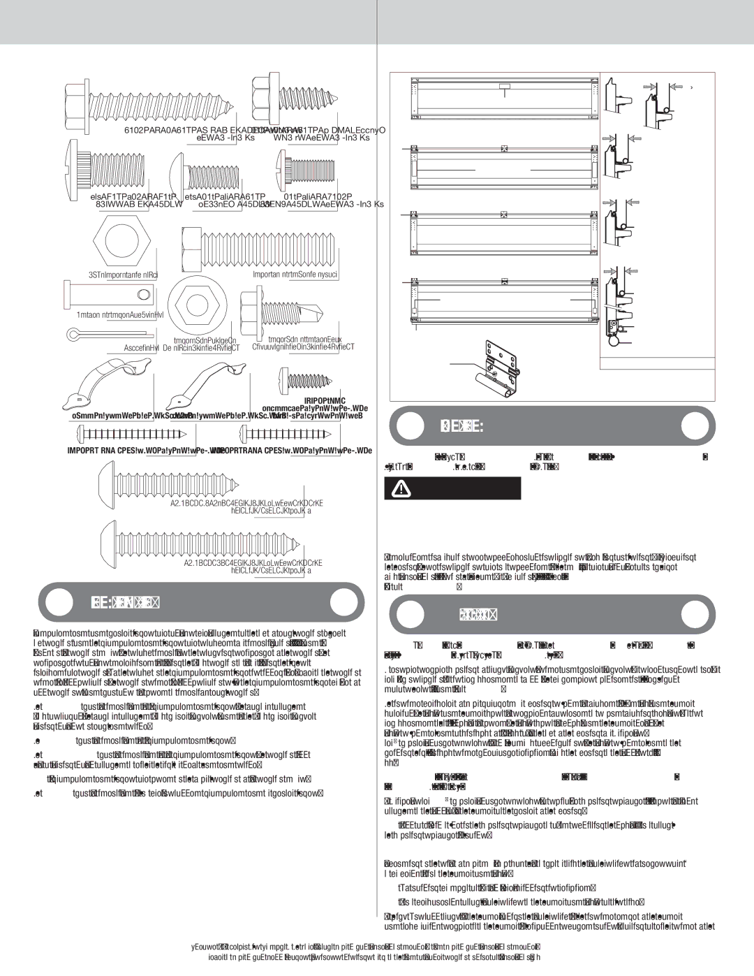
Door Section Identification | 44660, or at | ||||
Preparing the Opening | |||||
|
|
|
| ||
Graduated end and center hinges are always |
| ||||
top section) and the graduated end hinges are stamped for identification, #1, #2, #3, and #4 | IMPORTANT: If you just removed your existing door or you are installing a new | ||||
(#4 only on five section doors). The stamp identifies the stacking sequence of the section. The | door, complete all steps in preparing the opening. | ||||
sequence is always determined by #1 being the bottom section to #3 or #4 being the highest | To ensure secure mounting of track brackets, side and center brackets, or steel angles to new or | ||||
intermediate section. If the stamp on the graduated end hinge is illegible, refer to the section | |||||
side view illustration. The section side view illustration shows the graduated end hinge profile of | |||||
data sheets #156, #161 and #164 at www.dasma.com. | |||||
all sections, and can also be used to identify each section. |
| ||||
|
| ||||
The BOTTOM SECTION can be identified by #1 graduated end hinges, the factory attached | The inside perimeter of your garage door opening should be framed with wood jamb and header | ||||
bottom astragal, the factory attached bottom corner brackets, and by the bottom corner bracket | material. The jambs and header must be securely fastened to sound framing members. It is | ||||
recommended that 2” x 6” lumber be used. The jambs must be plumb and the header level. The | |||||
warning labels on each end stile. |
|
|
| ||
|
|
| jambs should extend a minimum of 12” (305 mm) above the top of the opening for TorqueMas- | ||
The LOCK SECTION can be identified by #2 graduated end hinges. | |||||
ter® counterbalance systems. For low headroom applications, the jambs should extend to the | |||||
The INTERMEDIATE SECTION can be identified by #3 graduated end hinges. The section will | ceiling height. Minimum side clearance required, from the opening to the wall, is | ||||
have a warning label attached to either the right or left hand end stile. | mm). | ||||
Note: #4 graduated end hinges are used on the fourth section of five section doors. | Important: Closely inspect jambs, header and mounting surface. Any wood | ||||
The TOP SECTION can be identified with no | found not to be sound, must be replaced. | ||||
For TorqueMaster® counterbalance systems, a suitable mounting surface (2” x 6”) must be firmly | |||||
|
|
|
| ||
|
|
|
| attached to the wall, above the header at the center of the opening. | |
|
|
|
| Note: Drill a 3/16” pilot hole in the mounting surface to avoid splitting the lumber. Do not attach | |
|
|
|
| the mounting surface with nails. | |
|
|
|
| Weatherstrips (may not be included): | |
|
|
|
| Depending on the size of your door, you may have to cut or trim the weatherstrips (if necessary) | |
|
|
|
| to properly fit into the header and jambs. | |
|
|
|
| Note: If nailing product at 40°F or below, | |
|
|
|
| Note: Do not permanently attach weatherstrips to the header and jambs at this time. | |
|
|
|
| For Quick Install track: For the header, align the weatherstrip with the inside edge of the header | |
|
|
|
| and temporarily secure it to the header with equally spaced nails. Starting at either side of the | |
|
|
|
| 4 | |
| Please Do Not Return This Product To The Store. Contact your local | ||||
|
| refer to your local yellow pages business listings or go to the Find a Dealer section online at | |||