Parts Breakdown
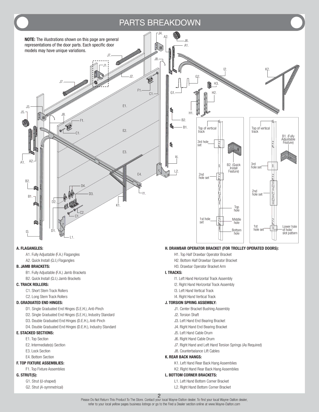
NOTE: The illustrations shown on this page are general representations of the door parts. Each specific door models may have unique variations.
J7.
J1.
J7.
![]() J4. A2.
J4. A2.
J8.![]()
J2.
F1. | C1. | G1. |
| ||
|
|
J6.
A1.
I2.
G2. |
H3. |
H2. |
K2.
J3. |
| E1. |
J5. | J8. |
|
|
| |
| F1. |
|
| C1. | E2. |
|
|
E3.
I4.
A1. A2.
| H1. |
|
|
|
| |||||
B2. |
|
|
|
|
|
|
|
|
|
|
|
|
|
|
|
|
|
|
|
| |
B1. |
| Top of |
| vertical |
|
|
|
| ||
|
|
|
|
| ||||||
|
| track |
|
|
|
| ||||
|
| 3rd hole |
|
|
|
|
| |||
|
|
|
|
|
| |||||
|
| set |
|
|
|
|
|
| ||
|
|
|
|
|
| |||||
|
|
|
|
|
|
|
|
|
|
|
|
|
|
|
|
|
|
|
|
|
|
B2. (Quick
Top of vertical track
B1. (Fully
Adjustable
Feature)
3rd
|
| E4. | L2. |
|
|
| |
B2. |
|
|
|
| D4. |
|
|
B1. | D3. |
| I1. |
|
|
|
D2.
K1.
2nd hole set
Install
Feature)
hole set
2nd hole set
C2.
![]() C1.
C1.
I3.D1.
![]() L1.
L1.
|
|
|
|
| Top |
1st hole |
|
|
| hole | |
|
|
| Middle | ||
|
|
| |||
|
|
| |||
set |
|
|
|
| hole |
|
|
|
|
| Bottom |
|
|
|
|
| hole |
1st |
|
|
| Lower hole | |
|
|
| |||
hole set |
|
|
|
| of hole/ |
|
| ||||
|
|
|
|
| slot pattern |
A. Flagangles: | H. Drawbar Operator Bracket (For Trolley Operated Doors): | ||
A1. | Fully Adjustable (F.A.) Flagangles | H1. Top Half Drawbar Operator Bracket | |
A2. | Quick Install (Q.I.) Flagangles | H2. Bottom Half Drawbar Operator Bracket | |
B. Jamb Brackets: | H3. Drawbar Operator Bracket Arm | ||
B1. | Fully Adjustable (F.A.) Jamb Brackets | I. Tracks: | |
B2. | Quick Install (Q.I.) Jamb Brackets | I1. Left Hand Horizontal Track Assembly | |
C. Track Rollers: | I2. Right Hand Horizontal Track Assembly | ||
C1. | Short Stem Track Rollers | I3. Left Hand Vertical Track | |
C2. | Long Stem Track Rollers | I4. Right Hand Vertical Track | |
D. Graduated End Hinges: | J. Torsion Spring Assembly: | ||
D1. | Single Graduated End Hinges (S.E.H.), | J1. | Center Bracket Bushing Assembly |
D2. | Single Graduated End Hinges (S.E.H.), Industry Standard | J2. Torsion Shaft | |
D3. | Double Graduated End Hinges (D.E.H.), | J3. | Left Hand End Bearing Bracket |
D4. | Double Graduated End Hinges (D.E.H.), Industry Standard | J4. | Right Hand End Bearing Bracket |
E. Stacked Sections: | J5. Left Hand Cable Drum | ||
E1. Top Section | J6. | Right Hand Cable Drum | |
E2. Intermediate(s) Section | J7. | Right Hand and Left Hand Torsion Springs (As Required) | |
E3. Lock Section | J8. | Counterbalance Lift Cables | |
E4. Bottom Section | K. Rear Back Hangs: | ||
F. Top Fixture Assemblies: | K1. Left Hand Rear Back Hang Assemblies | ||
F1. Top Fixture Assemblies | K2. Right Hand Rear Back Hang Assemblies | ||
G. Strut(s): | L. Bottom Corner Brackets: | ||
G1. | Strut | L1. | Left Hand Bottom Corner Bracket |
G2. | Strut | L2. | Right Hand Bottom Corner Bracket |
2
Please Do Not Return This Product To The Store. Contact your local
refer to your local yellow pages business listings or go to the Find a Dealer section online at