Set screws

Coupler

Black cable drum

and Lock

halves

(right hand side)

nut


Center


Torsion


coupler


keyed

Set

assembly


shaft


collar


Coupler

(3) 3/8” - 16 x 1-3/4” Hex head screws

Right hand wound,

halves

red winding cone

and (3) 3/8” - 16 Nylon hex lock nut

Center

(right hand side)


bearing

Key


Red cable drum


Set screws


(left hand side)


Center bearing bracket(s)

Coupler

assembly

Center bearing inside

torsion spring

Torsion

spring

Center

bearing

Torsion

keyed

shaft

Center

and Lock nut

bearing

Key

Left hand wound,


black winding cone


Set collar (left hand side)

Coupler halves

Torsion keyed shaft


(2) 3/8”-16 Nuts

Typical center bracket


assembly

assemblied

Equal spacing

Center bearing


brackets


Torsion

Center


keyed

bearing

Coupler

shaft


Torsion

halve


keyed


Right hand end

shaft


bearing bracket


Equal


Torsion spring

Stationary spring cone

Torsion spring

(2)3/8”-16 x 1-1/2” Hex head bolts

spacing


Left hand wound,


black winding cone

Set collar

(left hand side)


Left hand end

bearing bracket

20

Torsion Spring Attachment


Center bearing brackets Coupler assembly

Set screws

Torsion

keyedLock nuts shaft

(3) 3/8” - 16 x 1-3/4”

hex head screws


(3) 3/8” - 16


nylon hex lock

Torsion

nuts

keyed


shaft


Coupler


halves

Tools: Step Ladder, 1/2” Wrench

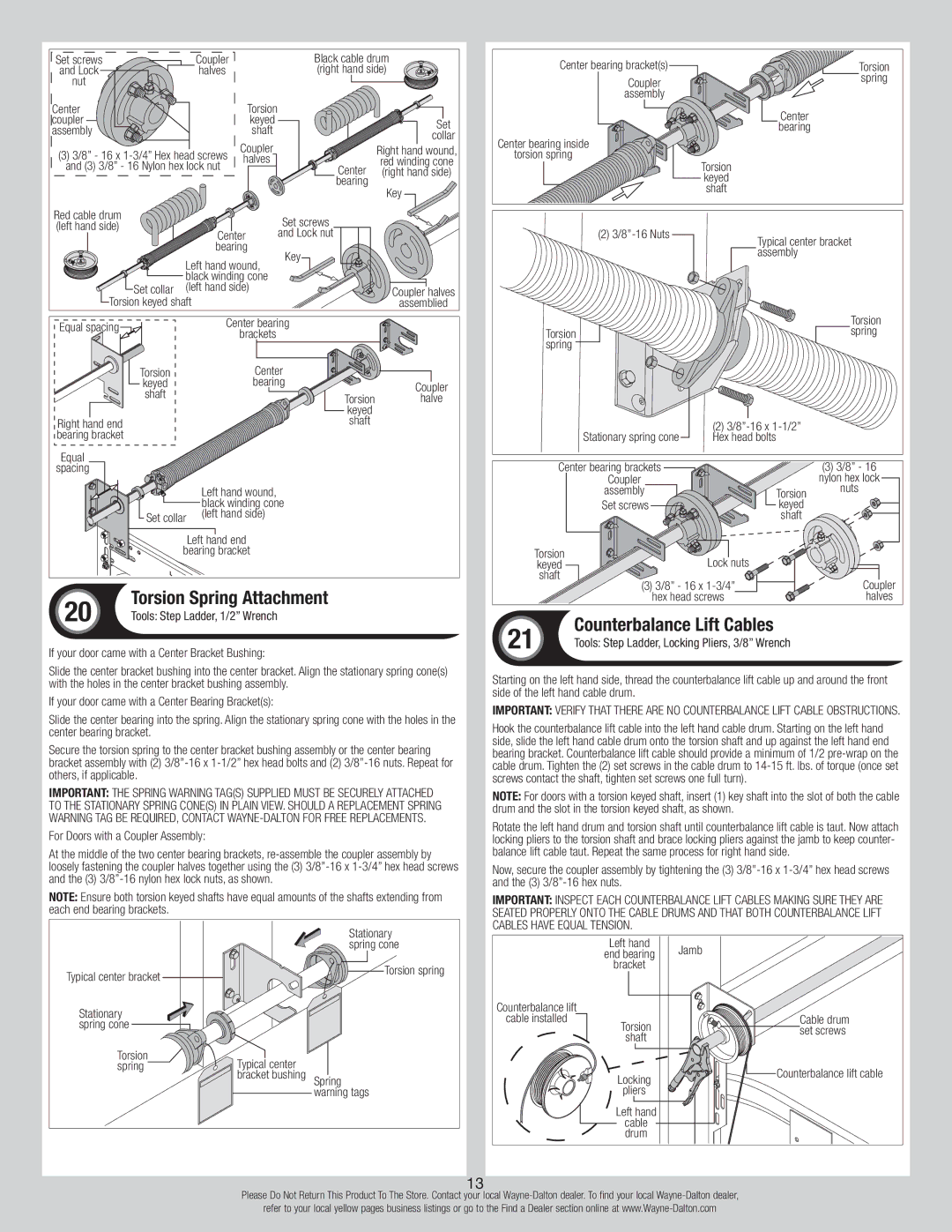
If your door came with a Center Bracket Bushing:

Slide the center bracket bushing into the center bracket. Align the stationary spring cone(s) with the holes in the center bracket bushing assembly.

If your door came with a Center Bearing Bracket(s):

Slide the center bearing into the spring. Align the stationary spring cone with the holes in the center bearing bracket.

Secure the torsion spring to the center bracket bushing assembly or the center bearing bracket assembly with (2) 3/8”-16 x 1-1/2” hex head bolts and (2) 3/8”-16 nuts. Repeat for others, if applicable.

IMPORTANT: The spring warning tag(s) supplied must be securely attached to the stationary spring cone(s) in plain view. Should a replacement spring warning tag be required, contact Wayne-Dalton for free replacements.

For Doors with a Coupler Assembly:

At the middle of the two center bearing brackets, re-assemble the coupler assembly by loosely fastening the coupler halves together using the (3) 3/8”-16 x 1-3/4” hex head screws and the (3) 3/8”-16 nylon hex lock nuts, as shown.

NOTE: Ensure both torsion keyed shafts have equal amounts of the shafts extending from each end bearing brackets.

Stationary spring cone

Typical center bracket

Torsion spring


Stationary spring cone

Torsion

springTypical center bracket bushing Spring

warning tags

21

Counterbalance Lift Cables

Tools: Step Ladder, Locking Pliers, 3/8” Wrench

Starting on the left hand side, thread the counterbalance lift cable up and around the front side of the left hand cable drum.

IMPORTANT: Verify that there are no counterbalance lift cable obstructions.

Hook the counterbalance lift cable into the left hand cable drum. Starting on the left hand side, slide the left hand cable drum onto the torsion shaft and up against the left hand end bearing bracket. Counterbalance lift cable should provide a minimum of 1/2 pre-wrap on the cable drum. Tighten the (2) set screws in the cable drum to 14-15 ft. lbs. of torque (once set screws contact the shaft, tighten set screws one full turn).

NOTE: For doors with a torsion keyed shaft, insert (1) key shaft into the slot of both the cable drum and the slot in the torsion keyed shaft, as shown.

Rotate the left hand drum and torsion shaft until counterbalance lift cable is taut. Now attach locking pliers to the torsion shaft and brace locking pliers against the jamb to keep counter- balance lift cable taut. Repeat the same process for right hand side.

Now, secure the coupler assembly by tightening the (3) 3/8”-16 x 1-3/4” hex head screws and the (3) 3/8”-16 hex nuts.

IMPORTANT: Inspect each counterbalance lift cables making sure they are seated properly onto the cable drums and that both counterbalance lift cables have equal tension.


Left hand

Jamb


end bearing


bracket


Counterbalance lift


cable installed

Torsion

Cable drum


set screws


shaft


Locking

Counterbalance lift cable


pliers


Left hand


cable


drum


13

Please Do Not Return This Product To The Store. Contact your local Wayne-Dalton dealer. To find your local Wayne-Dalton dealer,

refer to your local yellow pages business listings or go to the Find a Dealer section online at www.Wayne-Dalton.com

Page 13
Image 13
Wayne-Dalton 42, 43, 40, 47, 45 Torsion Spring Attachment, If your door came with a Center Bracket Bushing

45, 42, 47, 40, 43 specifications

Wayne-Dalton is renowned for its innovative approach to garage doors, and the series 45, 43, 42, 47, and 40 exemplify their commitment to quality and performance. Each model is engineered with unique features that cater to both aesthetic preferences and functional requirements, ensuring homeowners find the perfect match for their needs.

The Wayne-Dalton 45 model stands out with its distinctive design, offering a variety of panels and styles that can complement different architectural themes. This model utilizes durable materials such as steel and aluminum, providing excellent resistance against the elements while maintaining an attractive appearance. Its insulated version incorporates polyurethane foam, which effectively enhances energy efficiency, improving home comfort.

The 43 series is characterized by its robust construction and design flexibility. With multiple color options and textures, homeowners can easily personalize their garage doors. This model also highlights Wayne-Dalton’s innovative TorqueMaster® torsion spring system, which simplifies installation and enhances safety by keeping the spring contained within a steel tube.

The 42 model showcases a contemporary aesthetic, featuring sleek lines and modern designs that appeal to today’s homeowners. Constructed with high-quality materials, the 42 model offers excellent thermal insulation properties, reducing energy costs and increasing overall home efficiency. Its advanced weather sealing system prevents air and water infiltration, ensuring the interior remains comfortable regardless of external conditions.

The Wayne-Dalton 47 is designed for those seeking a more rustic or traditional look. This model mimics the appearance of wood with its faux-wood options while providing the durability of steel. Its insulation technology allows for significant energy savings, making it a sensible choice for regions with extreme weather conditions.

Lastly, the 40 model is recognized for its simplicity and reliability. It combines functionality with affordability, making it ideal for homeowners seeking an economical option without sacrificing quality. Its design allows for a smooth operation, and its long-lasting materials ensure that it withstands the test of time.

In summary, the Wayne-Dalton 45, 43, 42, 47, and 40 models showcase a variety of designs, technologies, and characteristics that cater to different homeowner preferences. From energy efficiency and security features to aesthetic choices, Wayne-Dalton continues to lead the market in garage door solutions. Whether prioritizing style, durability, or value, there is a Wayne-Dalton model that fits every homeowner's needs.