Operating Instructions and Parts Manual
Installation |
|
| IMPORTANT: Make sure there is | so that the pump switches on with | |||||||||||||||
|
|
|
|
| adequate room for float switch to move | approximately 14” of water in the sump. | |||||||||||||
1. A ground fault circuit interrupter | |||||||||||||||||||
freely during operation. | 3. While the pump is draining the pit, | ||||||||||||||||||
(GFCI) is required. |
|
| |||||||||||||||||
|
|
|
|
|
|
|
|
|
|
|
|
| |||||||
|
| 7. | Protect electrical cord from sharp | verify that the discharge piping is | |||||||||||||||
2. This pump is for use on 120 Volt | |||||||||||||||||||
| objects, hot surfaces, oil and | carrying the water to a point several | |||||||||||||||||
(single phase), 60 hz, 15 amp service |
| ||||||||||||||||||
| chemicals. Avoid kinking the | feet away from the foundation. | |||||||||||||||||
and is equipped with a 3 conductor |
| ||||||||||||||||||
| cord and replace damaged cords | 4. If the pump discharge line is | |||||||||||||||||
cord and a 3 prong grounding plug. |
| ||||||||||||||||||
| immediately. | exposed to freezing temperature, | |||||||||||||||||
3. Install pump in a sump pit with |
| ||||||||||||||||||
8. | A sump pit cover must be installed | the exposed line must be pitched to | |||||||||||||||||
minimum size as shown (See Figure | |||||||||||||||||||
| to prevent debris from clogging or | drain. Trapped water will freeze and | |||||||||||||||||
1). Construct sump pit of tile, |
| ||||||||||||||||||
| damaging the pump. | damage the pump. | |||||||||||||||||
concrete, steel or plastic. |
| ||||||||||||||||||
|
|
|
|
|
|
|
|
|
|
|
|
|
| ||||||
4. Locate unit on a solid, level |
|
|
|
| Risk of |
|
|
|
| Maintenance | |||||||||
|
|
|
| ||||||||||||||||
|
|
| |||||||||||||||||
|
|
|
| electrical |
|
|
|
| |||||||||||
foundation. Do not place pump |
|
|
|
|
|
|
|
| |||||||||||
|
|
|
|
|
|
|
|
|
|
| |||||||||
shock! This pump is supplied |
|
|
|
|
|
|
| ||||||||||||
directly on clay, earth, gravel or |
|
|
|
|
|
|
| ||||||||||||
with a grounding conductor |
|
|
|
|
| Always |
| ||||||||||||
sandy surface. These surfaces contain |
|
|
|
|
|
| |||||||||||||
|
|
|
|
|
|
|
|
|
|
| disconnect the electrical |
| |||||||
and grounding type attachment plug. Use |
| ||||||||||||||||||
small stones, gravel, sand, etc. that |
| ||||||||||||||||||
a grounded GFCI receptacle to reduce the | supply before attempting to |
| |||||||||||||||||
may clog or damage the pump and | risk of fatal electrical shock. | install, service, relocate or |
| ||||||||||||||||
| |||||||||||||||||||
cause pump failure (See Figure 1). | Never cut off the round grounding | perform any maintenance. If the power | |||||||||||||||||
5. (Optional) Thread check valve (not | source is out of sight, lock and tag | ||||||||||||||||||
prong. Cutting the cord or plug will | |||||||||||||||||||
included) into pump body carefully | in the open (off) position to prevent | ||||||||||||||||||
void the warranty and make the | |||||||||||||||||||
unexpected power application. Failure | |||||||||||||||||||
to avoid stripping or cross threading. | |||||||||||||||||||
pump inoperable. | |||||||||||||||||||
to do so could result in fatal electrical | |||||||||||||||||||
Do not use pipe joint sealant. | |||||||||||||||||||
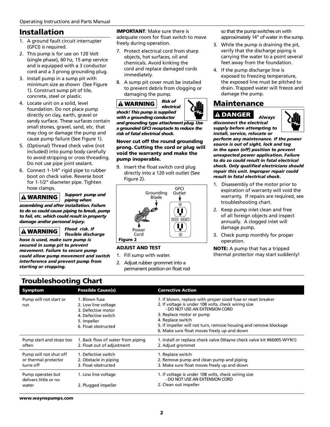
9. | Insert the float switch cord plug | shock. Only qualified electricians should | |||||||||||||||||
6. Connect | |||||||||||||||||||
| directly into a 120 volt outlet (See | repair this unit. Improper repair could | |||||||||||||||||
boot on check valve. Reverse boot |
| result in fatal electrical shock. | |||||||||||||||||
| Figure 2). |
|
|
|
|
|
|
|
| ||||||||||
for |
|
|
|
|
|
|
|
|
| 1. Disassembly of the motor prior to | |||||||||
|
|
|
|
|
|
|
|
|
|
| |||||||||
hose clamps. |
|
|
|
|
|
|
|
|
|
|
|
|
| ||||||
|
|
|
|
| Grounding | GroundedGFCI |
|
| expiration of warranty will void the | ||||||||||
|
| Support pump and |
|
|
| Outlet |
|
| |||||||||||
|
|
|
|
|
|
| warranty. If repairs are required, see | ||||||||||||
|
|
|
|
| Blade |
| |||||||||||||
|
| piping when |
|
|
|
| |||||||||||||
|
|
|
|
|
|
|
|
|
|
|
|
| troubleshooting chart. | ||||||
assembling and after installation. Failure |
|
|
|
|
|
|
|
|
|
|
| ||||||||
|
|
|
|
|
|
|
|
|
|
| 2. Keep pump inlet clean and free | ||||||||
to do so could cause piping to break, pump |
|
|
|
|
|
|
|
|
|
|
| ||||||||
to fail, etc. which could result in property |
|
|
|
|
|
|
|
|
|
|
| of all foreign objects and inspect | |||||||
damage and/or personal injury. |
|
|
|
|
| TEST | RESET |
|
|
| annually. A clogged inlet will | ||||||||
|
|
|
|
|
|
|
|
|
|
| |||||||||
|
| Flood | risk. If |
| Power |
|
|
|
|
|
|
|
| damage pump. | |||||
|
|
|
|
|
|
|
|
|
|
| |||||||||
|
|
|
|
|
|
|
|
|
|
|
|
|
| ||||||
|
| flexible discharge |
| Cord |
|
|
|
|
|
|
|
| 3. Check pump monthly for proper | ||||||
|
|
|
|
|
|
|
|
|
|
| |||||||||
|
|
|
|
|
|
|
|
|
|
| |||||||||
hose is used, make sure pump is | Figure 2 |
|
|
|
|
|
|
|
| operation. | |||||||||
secured in sump pit to prevent | Adjust and Test | NOTE: A pump that has a tripped | |||||||||||||||||
movement. Failure to secure pump | |||||||||||||||||||
1. Fill sump with water. | thermal protector may start suddenly! | ||||||||||||||||||
could allow pump movement and switch | |||||||||||||||||||
interference and prevent pump from | 2. | Adjust rubber grommet into a |
|
|
| ||||||||||||||
starting or stopping. |
|
|
| permanent position on float rod |
|
|
| ||||||||||||
|
|
|
|
|
|
|
|
| |||||||||||
|
|
|
|
|
|
|
|
|
|
|
|
|
|
| |||||
Troubleshooting Chart |
|
|
|
|
|
|
|
|
|
|
|
|
|
| |||||
Symptom | Possible Cause(s) |
|
|
|
| Corrective Action |
|
|
| ||||||||||
Pump will not start or | 1. Blown fuse |
|
|
|
| 1. If blown, replace with proper sized fuse or reset breaker | |||||||||||||
run | 2. Low line voltage |
|
|
|
| 2. If voltage is under 108 volts, check wiring size | |||||||||||||
|
|
| 3. Defective motor |
|
|
|
| - DO NOT USE AN EXTENSION CORD | |||||||||||
|
|
| 4. Defective switch |
|
|
|
| 3. Replace motor or pump |
|
|
| ||||||||
|
|
| 5. Impeller |
|
|
|
| 4. Replace switch |
|
|
| ||||||||
|
|
| 6. Float obstructed |
|
|
|
| 5. If impeller will not turn, remove housing and remove blockage | |||||||||||
|
|
|
|
|
|
|
|
| 6. Make sure float moves freely up and down | ||||||||||
|
|
|
|
|
|
|
|
| |||||||||||
Pump start and stops too | 1. Back flow of water from piping |
| 1. Install or replace check valve (Wayne check valve kit | ||||||||||||||||
often | 2. Float out of adjustment |
| 2. Adjust grommet |
|
|
| |||||||||||||
|
|
|
|
|
|
|
|
|
|
|
|
|
| ||||||
Pump will not shut off | 1. Defective switch |
|
|
|
| 1. Replace switch |
|
|
| ||||||||||
or thermal protector | 2. Obstacle in piping |
|
|
| 2. Remove pump and clean pump and piping | ||||||||||||||
turns off | 3. Float obstructed |
|
|
|
| 3. Make sure float moves freely up and down | |||||||||||||
|
|
|
|
|
|
|
|
|
|
| |||||||||
Pump operates but | 1. Low line voltage |
|
|
|
| 1. If voltage is under 108 volts, check wiring size | |||||||||||||
delivers little or no |
|
|
|
|
|
| - DO NOT USE AN EXTENSION CORD | ||||||||||||
water | 2. Plugged impeller |
|
|
| 2. Clean out impeller |
|
|
| |||||||||||
www.waynepumps.com
2