Operating Instructions and Parts Manual | Deep Well Submersible Pump |
Installation
WIRE SPLICING
Splice wire to motor leads. Use only copper wire for connections to pump/ motor assembly and control box.
Heat shrink splice instructions (wire sizes No. 14, 12 and 10 AWG [2, 3 and 5mm2]):
1.Remove 3/8" (9.5 mm) insulation from ends of motor leads and power supply wires.
2.Place heat shrink tubing over motor leads. Position tubing between power supply and motor.
3.Match colors of supply wires with colors of motor leads.
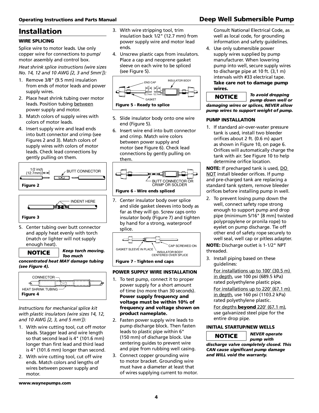
4.Insert supply wire and lead ends into butt connector and crimp (see Figures 2 and 3). Match colors of supply wires with colors of motor leads. Check lead connections by gently pulling on them.
1/2 inch | BUTT CONNECTOR | |
(12.7mm) | ||
| ||
Figure 2 |
|
INDENT HERE |
Figure 3 |
5.Center tubing over butt connector and apply heat evenly with torch (match or lighter will not supply enough heat).
Keep torch moving. Too much
concentrated heat may damage tubing (see Figure 4).
CONNECTOR |
HEAT SHRINK TUBING |
Figure 4 |
Instructions for mechanical splice kit with plastic insulators (wire sizes 14, 12, and 10 AWG [2, 3, and 5 mm2]):
1.With wire cutting tool, cut off motor leads. Stagger lead and wire length so that second lead is 4" (101.6 mm) longer than first lead and third lead is 4" (101.6 mm) longer than second.
2.With wire cutting tool, cut off wire ends. Match colors and lengths of wires between power supply and motor.
3. With wire stripping tool, trim | ||
insulation back 1/2" (12.7 mm) from | ||
power supply wire and motor lead | ||
ends. |
|
|
4. Unscrew plastic caps from insulators. | ||
Place a cap and neoprene gasket | ||
sleeve on each wire to be spliced | ||
(see Figure 5). |
|
|
END CAP | INSULATOR BODY | |
| ||
1" | 1" |
|
2 | 2 |
|
12.7mm 12.7mm |
| |
GASKET |
| |
Figure 5 - Ready to splice | ||
5. Slide insulator body onto one wire | ||
end (Figure 5). |
|
|
6. Insert wire end into butt connector | ||
and crimp. Match wire colors | ||
between power supply and | ||
motor (see Figure 6). Check lead | ||
connections by gently pulling on | ||
them. |
|
|
| BUTT CONNECTOR OR | |
| CRIMP OR SOLDER | |
Figure 6 - Wire ends spliced | ||
7. Center insulator body over splice | ||
and slide gasket sleeves into body as | ||
far as they will go. Screw caps onto | ||
insulator body (Figure 7) and tighten | ||
by hand for a strong, waterproof | ||
splice. |
|
|
CAP SCREWED ON
GASKET SLEEVE IN PLACE
INSULATOR BODY
CENTERED OVER SPLICE
Figure 7 - Tighten end caps
POWER SUPPLY WIRE INSTALLATION
1.To test pump, connect it to proper power supply for a short amount of time (no more than 30 seconds).
Power supply frequency and voltage must be within 10% of frequency and voltage shown on product nameplate.
2.Fasten power supply wire leads to pump discharge block. Then fasten leads to plastic pipe within 6"
(150 mm) of discharge block. Use centering guides to prevent wire and pipe from rubbing well casing.
3.Connect copper grounding wire to motor bracket. Grounding wire must have a diameter at least that of wires supplying current to motor.
Consult National Electrical Code, as well as local code, for grounding information and safety guidelines.
4.Use only submersible power supply wires supplied by pump manufacturer. When lowering pump into well, secure supply wires to discharge pipe at 10 ft. (3,1 m) intervals with #33 electrical tape.
Take care not to damage pump wires.
To avoid dropping pump down well or
damaging wires or splices, NEVER allow pump wires to support weight of pump.
PUMP INSTALLATION
1.If standard
NOTE: If precharged tank is used, DO NOT install bleeder orifices. If pump and
2.To prevent losing pump down the well, connect safety rope strong enough to support pump and drop pipe (minimum 5/16" [8 mm] twisted polypropylene or pronila rope) to eyelet on pump discharge. Tie off other end of safety rope securely to well seal, well cap or pitless adapter.
NOTE: Discharge outlet is
3.Install piping based on these guidelines:
For installations up to 100’ (30.5 m) in depth, use 100 psi (689.5 kPa) rated polyethylene plastic pipe.
For installations up to 220’ (67.1 m) in depth, use 160 psi (1103.2 kPa) rated polyethylene plastic.
For depths beyond 220’ (67.1 m), use galvanized steel pipe for the entire drop pipe.
INITIAL STARTUP/NEW WELLS
Never operate pump with
discharge valve completely closed. This can cause significant pump damage and will void the warranty.
www.waynepumps.com
4