INSTALL WORK SURFACE AND SIDE BURNER
FOR THE PLATINUM SERIES II 3200 (CONTINUED)
Route the side burner hose around the tank panel so it will not interfere with the scale indicator rod.
The side burner hose is connected in the following manner:
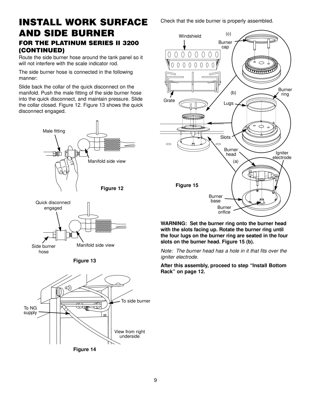
Slide back the collar of the quick disconnect on the manifold. Push the male fitting of the side burner hose into the quick disconnect, and maintain pressure. Slide the collar closed. Figure 12. Figure 13 shows the quick disconnect engaged.
Male fitting
Manifold side view
Check that the side burner is properly assembled.
Windshield(c)
Burner
cap
| (b) | Burner |
| ring | |
|
| |
Grate | Lugs |
|
|
|
Slots
Burner
headIgniter electrode
(a)
| Figure 12 | Figure 15 | |
|
| ||
|
| Burner | |
Quick disconnect |
| base | |
| Burner | ||
engaged |
| ||
|
| orifice | |
|
| WARNING: Set the burner ring onto the burner head | |
|
| with the slots facing up. Rotate the burner ring until | |
|
| the four lugs on the burner ring are seated in the four | |
Side burner | Manifold side view | slots on the burner head. Figure 15 (b). | |
Note: The burner head has a hole in it that fits over the | |||
hose |
| ||
| Figure 13 | igniter electrode. | |
| After this assembly, proceed to step “Install Bottom | ||
|
| ||
|
| Rack” on page 12. |
![]()
![]() To side burner
To side burner
To NG![]() supply
supply ![]()
View from right
underside
Figure 14
9