BUILT-IN SLEEVE GAS LINE LOCATIONS
Support tubes
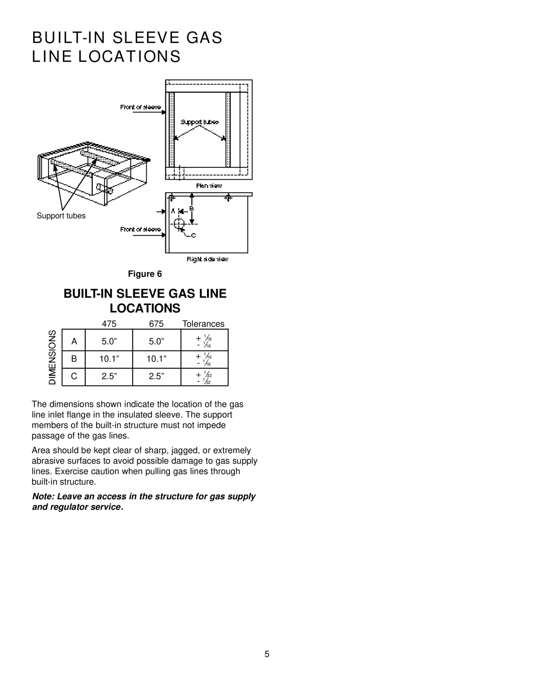
Figure 6
BUILT-IN SLEEVE GAS LINE
LOCATIONS
| 475 | 675 | Tolerances |
A | 5.0” | 5.0” | + 1⁄16 |
- 1⁄16 | |||
B | 10.1” | 10.1” | + 1⁄16 |
- 1⁄16 | |||
C | 2.5” | 2.5” | + 1⁄32 |
- 1⁄32 |
The dimensions shown indicate the location of the gas line inlet flange in the insulated sleeve. The support members of the
Area should be kept clear of sharp, jagged, or extremely abrasive surfaces to avoid possible damage to gas supply lines. Exercise caution when pulling gas lines through
Note: Leave an access in the structure for gas supply and regulator service.
5